The familiar hole-flanging layout appears straightforward: a punch enters a pilot hole, turns the surrounding metal into a short wall, and withdraws. The difficult part is making that sequence repeat without splitting the edge, dragging the collar or losing the required dimensions after release.
A conventional tool layout is a starting point for engineering review. Its suitability depends on the material, formed wall and complete stripping motion. The checks below explain why a valid-looking closed-die section can conceal a production problem.
What does hole flanging produce?
Hole flanging, also called hole extrusion in many sheet-metal shops, forms a short collar around an opening. This guide concerns the common route that starts from a pierced pilot hole. Other piercing-and-extrusion sequences need their own tooling review.
A collar can locate a mating feature or provide additional wall height for a specified thread. Forming the collar does not itself create that thread. Define the final bore, collar height and its measurement datum, allowable wall variation, and whether dimensions apply before or after tapping and finishing.
The hidden mistake: checking only the closed die
A hole-flanging section must work during entry, forming, unloading and stripping. A closed-die drawing shows only one of those conditions. It cannot establish the final free-state bore or prove that the part will clear the tool during the return stroke.
Trace which surfaces form the collar, which support the surrounding sheet and which remain in contact after the forming load falls. Check the punch, die and stripper through their actual relative motion, including dimensional variation. A profile described as standard still needs this application-specific review.
Why the wall thins while the hole edge turns
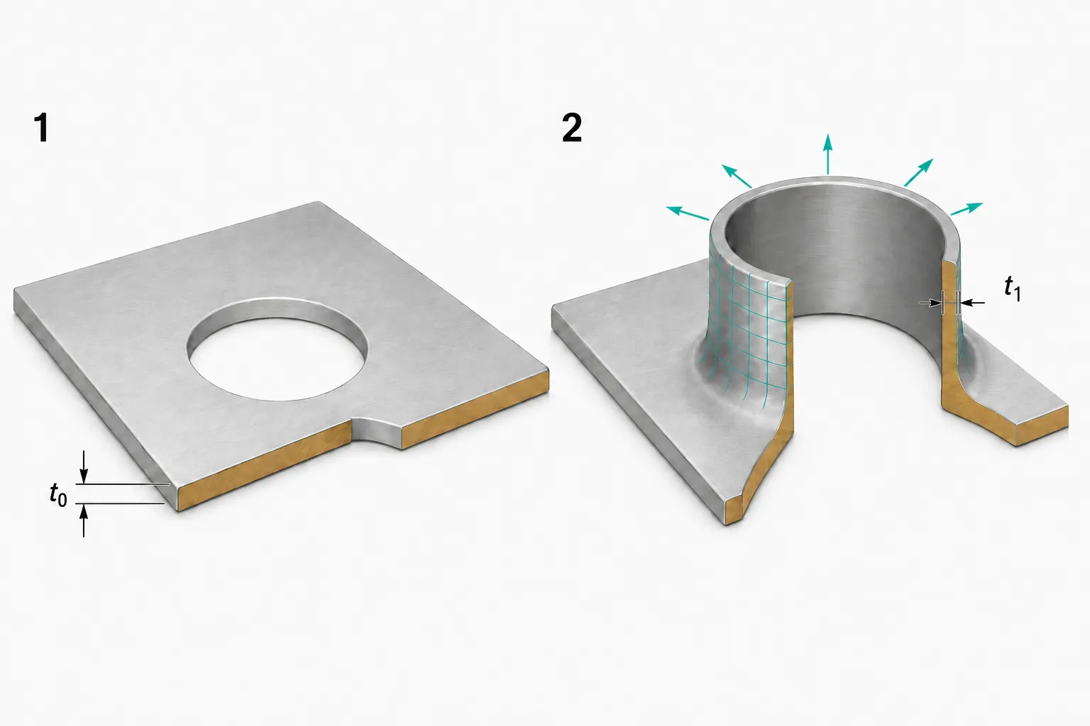
Hole flanging combines bending around the entry radius with stretching around the hole circumference. In the local bending component, the outer fibers extend while the inner fibers compress. The expanding hole edge also experiences circumferential stretch, so a two-dimensional bending sketch does not describe the complete strain state.
The collar edge can become thinner as metal is redistributed into a larger circumference and a raised wall. Plastic deformation approximately conserves metal volume before damage or separation; thinning is not material disappearing. Wall thickness can vary between the root and the lip and around the circumference.
Use the starting sheet thickness as a material specification, not as an assumed finished collar thickness. If the wall is functional, define where its minimum thickness must be checked. A smaller pilot hole may demand more edge expansion to reach the same final bore, increasing the need to check edge formability.
How springback can contribute to tool gripping
Springback is the elastic shape change that occurs as forming loads are removed. Depending on the geometry and stress history, a collar may change bore size or wall angle and maintain contact with the punch. The direction and amount of that change must be established for the actual part.
Thinning and springback are different mechanisms. Thinning changes the wall section through plastic flow; springback changes geometry during unloading. Compensating the punch diameter alone may not resolve both, and excessive compensation can damage the collar during stripping.
Tool gripping also has other possible causes: surface pickup, inadequate lubrication, misalignment, insufficient clearance or a poorly supported stripping action. Distinguish a dimensional interference from galling or an uneven load before modifying the tooling.
Review the punch working section, relief and entry profile
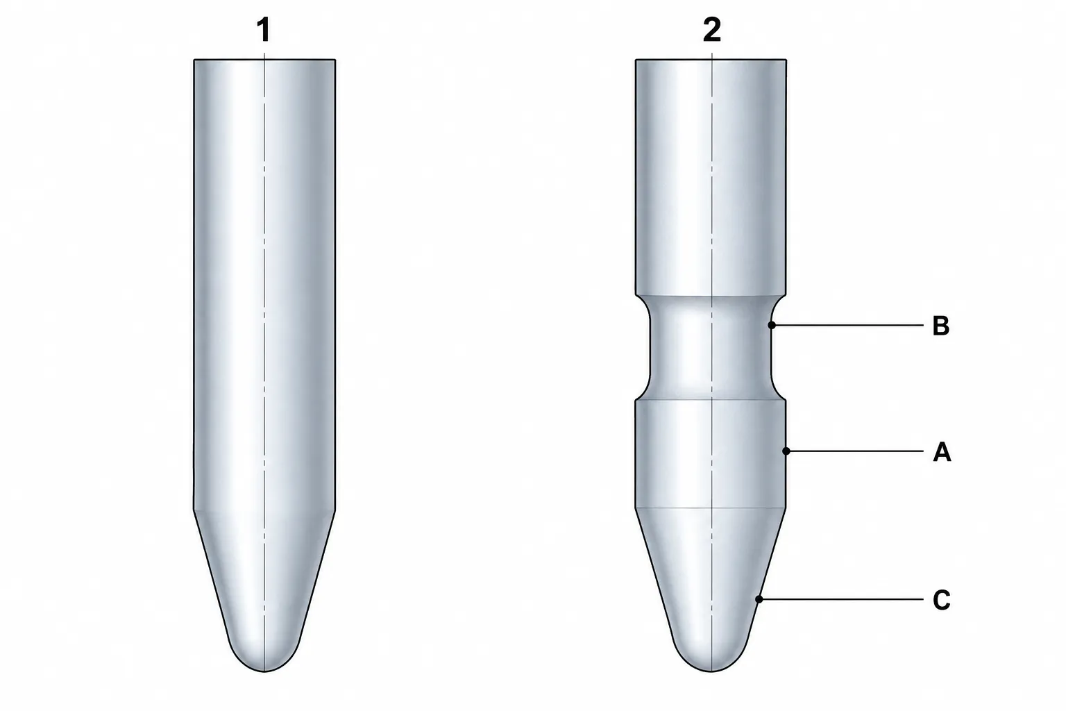
A useful punch review separates the section that forms or sizes the collar from adjacent surfaces that do not need to remain in contact. Relief near the punch root or behind a working land can reduce unwanted rubbing where the tooling arrangement permits it. Entry radii or tapered transitions influence how contact and deformation develop.
Relief is not an instruction to reduce the entire punch diameter. Preserve the required working profile and check support, strength, surface finish and smooth transitions. Verify that every larger section crossing the collar during withdrawal can pass without unacceptable re-expansion, scoring or tearing.
Evaluate profile changes with the intended stroke and shut height. Excessive travel can introduce unwanted ironing or loading; inadequate travel may leave the collar incompletely formed. Select these dimensions through the part and process review rather than copying a universal offset.
What a stepped die opening can change
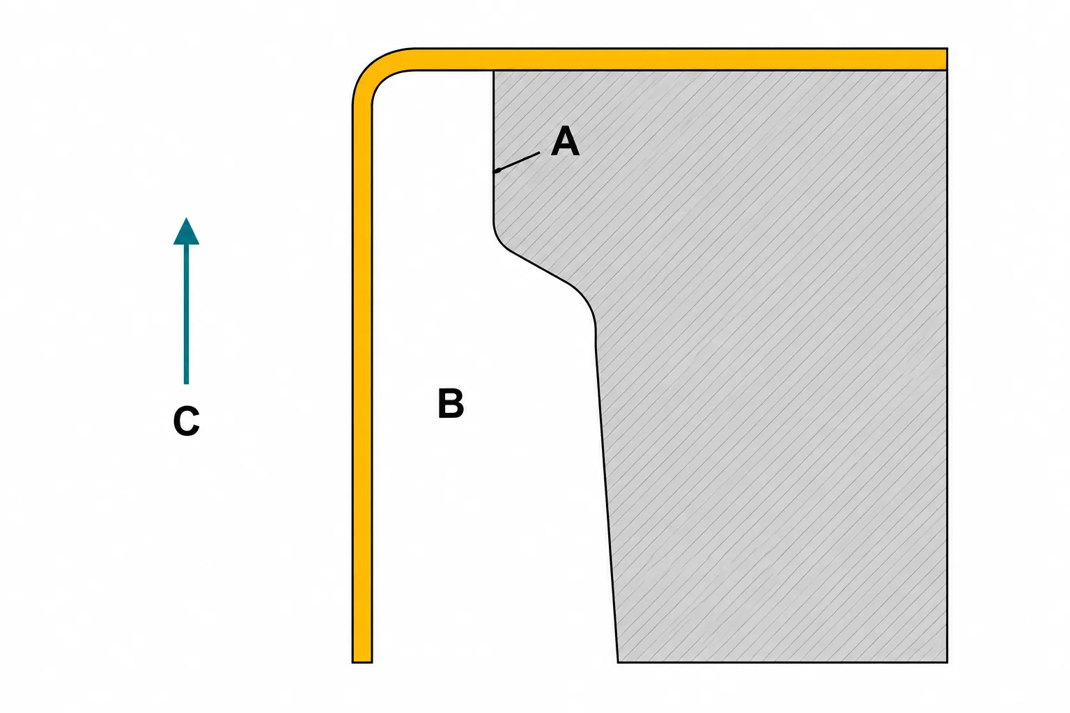
A stepped die opening can separate a region that controls forming from an adjacent region that provides clearance. Its purpose is to manage contact along the collar and provide a workable release path. The step location and direction must follow the actual tooling and part motion.
Review the local gap against the wall thickness expected at that height. Too little clearance can cause unintended ironing, high friction or wall damage. Too much clearance in a region that needs support can reduce dimensional control. The clearance used to pierce the pilot hole is a separate cutting parameter.
A die step does not restore a thinned wall. If a wall remains too thin, review material condition, pilot-hole geometry, collar height, radii and forming sequence. An abrupt or misplaced step can itself mark the part or obstruct stripping, so follow the full exit path before adopting the feature.
Pilot-hole quality is part of the forming design
The collar inherits the condition of its starting hole edge. Burrs, shear damage, tool wear and local defects can become crack-initiation sites when that edge is stretched. A formed-hole problem can therefore begin at the piercing operation, before the flanging punch touches the part.
WorldAutoSteel’s edge-stretching guidance explains that sheared-edge damage reduces local ductility and that measured hole expansion also depends on contact, friction and the test geometry. Total tensile elongation alone is not a sufficient prediction of a particular pierced edge’s performance.
Review pilot-hole size and concentricity, cutting clearance, burr direction and edge condition together with material grade, temper and thickness. If needed, evaluate an improved edge-preparation method or a revised forming sequence. Additional operations should have a demonstrated purpose and a clear inspection criterion.
How to verify that a tooling change works
Assess a hole-flanging change on fully released parts and through repeated forming and stripping cycles. A part that measures correctly while constrained by the tool is not evidence of free-state conformity. Where fit depends on an assembly condition, define that condition separately.
Record the material batch, tool revision, stroke and lubrication condition with the results. Compare the original and revised configuration under comparable conditions so that a material or setup change does not conceal the effect of the tooling change.
- Measure the released bore at specified heights and, where relevant, in multiple directions to detect taper or ovality.
- Check collar height from the agreed datum, wall angle and the surrounding sheet’s condition.
- Use an appropriate section or validated measurement method to examine minimum wall thickness and root-to-lip variation.
- Inspect the lip and root for cracks, and the bore and outside wall for scoring, pickup or stripping marks.
- Observe complete part release and any growth in stripping resistance or material buildup across the agreed trial run.
A threaded collar needs a separate connection check
If the collar will be tapped, its available wall and usable thread engagement must suit the selected thread and load. Overall collar height is not automatically the usable engagement length: lead-in, incomplete threads and transitions can reduce it.
Specify the thread, inspection stage and any assembly torque, strip-torque or pull-out requirement that the connection actually needs. A screw entering the hole does not by itself verify thread strength or repeated assembly performance. When the required engagement cannot be achieved reliably, compare a revised collar or a suitable separate fastener arrangement.
| Observation | Check first | Possible action to validate |
|---|---|---|
| Bore or wall angle changes after release | Free-state dimensions, tool constraint and springback | Review working profile and sizing strategy; remeasure after full release |
| Collar grips the tool or develops drag marks | Interference, pickup, lubrication, alignment and stripper support | Review relief and withdrawal path; correct contact or support problems |
| Lip splits or the wall becomes too thin | Pilot-hole edge, material condition, required expansion and local wall section | Review edge preparation, hole size, radii, height or forming sequence |
| Step marks or damage appear during stripping | Step position, clearance transitions and complete part motion | Revise the local transition or exit clearance while preserving forming support |
| Thread strips despite acceptable collar height | Minimum wall, complete thread engagement and specified connection load | Review thread process, usable engagement and the fastening arrangement |