Length relative to diameter
Length, diameter, grade and starting thickness determine the drawing route. The number of draws and any intermediate annealing must be assessed for your geometry.
Specify a light cylindrical sleeve around a sensor, valve or motor component. This design has two open ends and a continuous hollow bore. Start with the mating diameter, finished wall and length so the sleeve can be reviewed against your assembly.
Request a stainless steel sleeve quote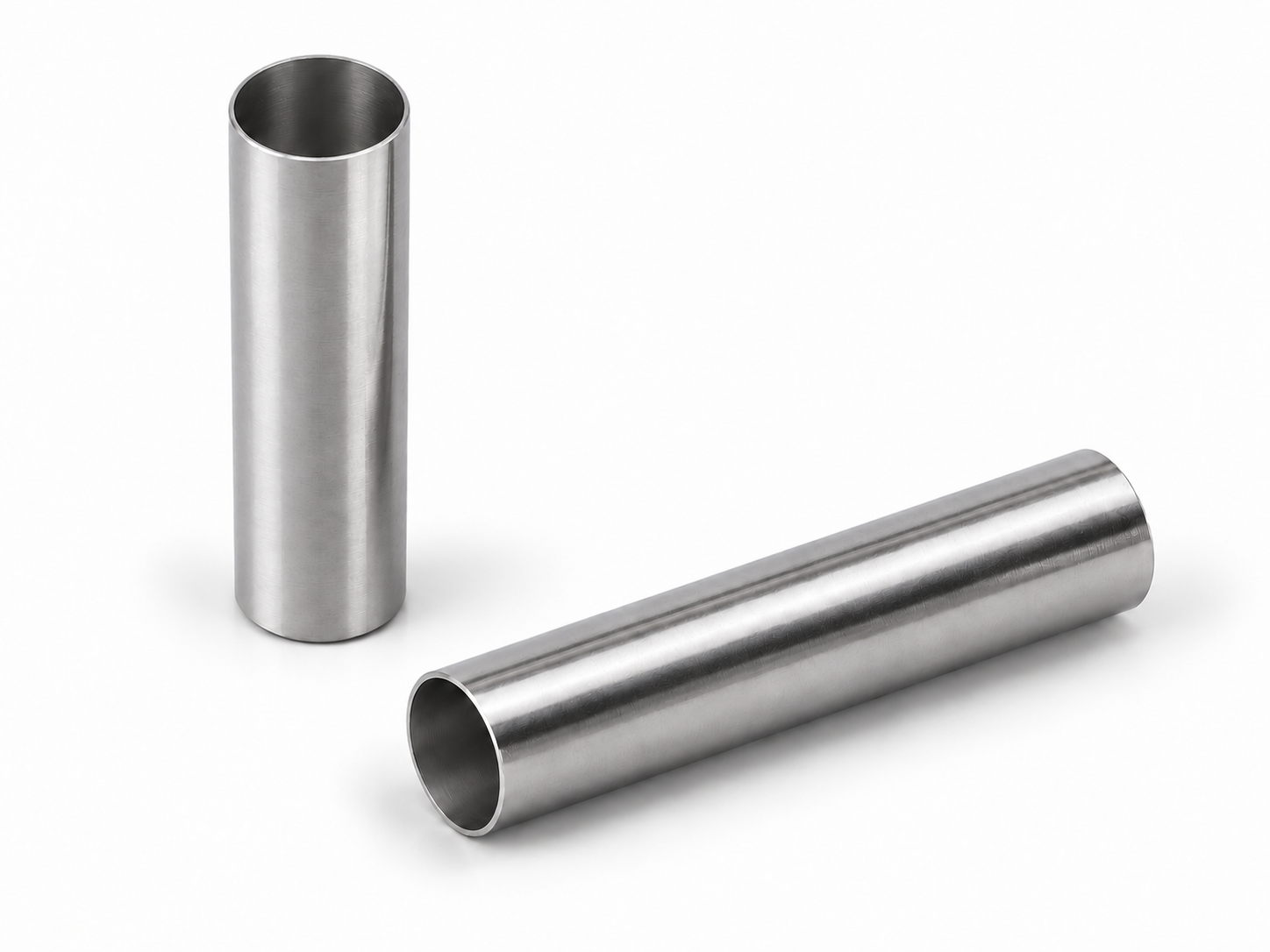
Inner diameter, outer diameter and wall thickness are linked. Identify the mating surface and the dimensions that must take priority instead of assigning the same tight tolerance to every dimension.
| Drawing item | What to specify |
|---|---|
| Bore and outside diameter | Mark the mating diameter, fit and measurement location. State whether the sleeve slides over, guides or is pressed onto another component. |
| Finished wall thickness | Specify the finished wall and permitted minimum after forming. Raw sheet thickness alone does not define the delivered wall. |
| Length and geometric tolerances | State finished length and any roundness, straightness or end-squareness requirements that affect assembly. Identify the datum. |
| Both open ends | Define the cut edges, burr direction and any edge break. Mark ends that will be inserted, joined or sealed. |
| Stainless grade and surface | Specify the grade and material condition, visible or contact surfaces, acceptable draw marks and any cleaning or passivation requirement. |
Length, diameter, grade and starting thickness determine the drawing route. The number of draws and any intermediate annealing must be assessed for your geometry.
Review where thinning or scoring could affect the sleeve. Set the minimum wall and surface criteria before approving samples.
A through-open sleeve requires an agreed opening, trimming and deburring route. End finishing must preserve the bore, length and joining surfaces.
A cylindrical protective sleeve around sensing or electronic components. Material, sensing clearance and assembly fit must match the sensor design.
An armature guide tube or isolation sleeve, where the design calls for one. Confirm magnetic properties, bore fit, joining and sealing requirements.
A protective sleeve for a rotor or magnets. Wall thickness, strength, operating speed and retention method must be checked for the motor design.
Use the drawing revision and the same measurement conditions for sample approval and batch inspection.
Identify bore and outside-diameter measurement positions, roundness and straightness limits. Agree whether a mating gauge or assembly trial is required.
Define measurement locations along the sleeve and around its circumference, plus the permitted minimum wall. Do not accept thickness from appearance alone.
Agree limits for burrs, draw marks, cracks and handling damage, and the protection needed to avoid dents or scratches during delivery.
Prioritize the diameter that mates with your component. Include the required clearance or interference and the assembled length. Bore, outside diameter and wall requirements must be reviewed together.
Sealing depends on the completed assembly, including end closures and joints. For valve or fluid service, specify medium, pressure, temperature, sealing method and the required test; the sleeve photo does not define those requirements.
Attach the 2D drawing and available 3D model, stainless grade, finished wall requirement, quantities and mating details. Mark the critical dimensions, end treatment and inspection requirements for the quotation.