A hole can have the right diameter and still cause trouble because too little metal remains beside it. A bracket can match the flat drawing yet miss its mating holes after bending. Good DFM looks at those relationships before the die makes them expensive to change.
This guide focuses on design choices. You can begin with a sketch or an unfinished drawing: identify what must fit, carry a load, touch a wire or make electrical contact. The supplier can then review manufacturing options with your team. Use the separate DFM preflight guide to record the decisions that must be settled for a tooling quotation.
What material information changes a stamping design?
A stamping design needs a material grade, delivery condition or temper, nominal thickness and allowed thickness variation. Those inputs affect punch loading, formability and springback. Two sheets described only as 'stainless steel' or 'aluminum' may behave differently even when their nominal thickness is the same.
Choose strength and formability together. A spring contact may need strength to retain its force, while a tightly bent cover needs enough local ductility to form without cracking. Changing to a softer condition can make forming easier but may change the part's function; treat it as a design decision.
If material selection is open, describe the load, environment, electrical function and intended finish. Ask for options with their tradeoffs. The material used for forming trials should represent the production condition, with any heat treatment carried out at its intended stage in the process.
How should hole-to-edge distance and hole spacing be measured?
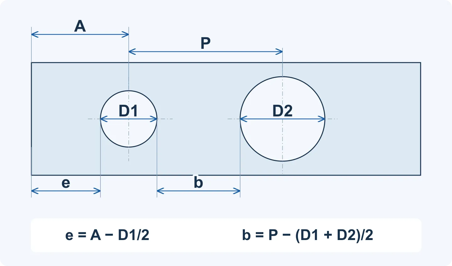
Measure hole-to-edge clearance between the hole's cut edge and the outer cut edge. Measure the bridge between two holes from their nearest cut edges. A center-to-edge distance or center pitch includes part of the hole itself, so it cannot be compared directly with a recommendation for the metal that remains.
For a round hole beside a straight edge, net clearance e = A − D1/2, where A is the perpendicular distance from the hole center to the outer edge. For two round holes, bridge b = P − (D1 + D2)/2, where P is their center-to-center distance. D1 and D2 are the two hole diameters.
Illustrative dimensions: a 4 mm hole with its center 4 mm from the outer edge leaves 4 − 4/2 = 2 mm of metal. A 4 mm hole and a 6 mm hole with centers 8 mm apart leave 8 − (4 + 6)/2 = 3 mm between them. These calculations describe geometry; whether the remaining metal is suitable depends on the material, thickness, cutting sequence and part function.
- For a slot, also check its narrow width, end radii and the shortest distance to neighboring cut edges.
- For curved outlines or irregular openings, use the actual shortest edge-to-edge distance rather than the round-hole equations.
- Ask whether extra clearance can be added in a non-functional area. Moving a locating hole requires an assembly check before the drawing changes.
How small can a punched hole or slot be?
There is no single minimum hole diameter that applies to every stamped metal part. Review the smallest punch dimension relative to sheet thickness, then consider material strength, punch support, cutting clearance and required edge quality. Dayton Lamina explains that small holes can increase compressive stress in the punch and change the sheared edge and burr. [1]
The reason is practical: a small punch must carry the cutting load through a small cross-section. The punch must also withdraw from the sheet and release the slug reliably. Simply specifying a harder punch material does not resolve every support, stripping or edge-quality problem.
If a small feature is functionally fixed, compare a supported punch arrangement or a separate operation. If it only provides clearance, ask whether a wider slot or larger hole would still work. The useful DFM outcome is an agreed geometry and route, not rejection based on a generic diameter-to-thickness rule.
How should bends, nearby holes and tool access be designed together?
Choose the inside bend radius for the actual grade, condition, thickness and forming method. The outside of a bend stretches, so an excessively sharp radius can crack even when the overall part looks simple. A radius equal to sheet thickness is a possible value to evaluate, not a safe rule for all materials. [2]
A hole near the bend can distort as the surrounding metal forms. State the reference used for its distance: the start of the curved bend on the finished part, the theoretical sharp corner and the bend centerline on the flat pattern are different locations. Review the final hole position relative to the mating face, not only its location before bending.
- Move the opening away from the bend where function permits, or compare piercing after forming if the tooling can reach and support it.
- Use bend relief where adjacent material would otherwise tear or interfere, but review its effect on stiffness, appearance and any sealing edge.
- Check short flanges, return bends and opposing walls for punch access, support and part removal. A shape that can be drawn in CAD may need a different operation sequence.
- For material with direction-dependent bendability, record the rolling direction and review it against the bend axes. Do not assume one nesting orientation suits every bend.
Why does the bend angle change after the press opens?
Springback is elastic recovery when the forming load is removed. It can change the angle, curve a wall or twist a part. Material strength after forming, elastic modulus, geometry and loading history all influence the result; 'harder metal springs back more' is too incomplete to select a bend design. [3]
Tooling may use overbending, a revised forming sequence or a later sizing operation to reach the required final shape. Making the radius sharper solely to reduce springback can increase cracking risk. Agree which finished angle or hole-to-face relationship matters, then validate it with representative samples.
For a flexible bracket, state whether that relationship is checked loose or under defined assembly restraint. Pressing the part flat during inspection can conceal a free-state fit problem. The supports and holding conditions need to match the requirement. [4]
What should be specified about edges, tolerances and finishing?
Specify the result needed at the functional feature. A cable opening should not damage insulation; a mating flange should seat; a grounding contact needs an appropriate conductive path. You can circle those areas on a drawing or photo without first selecting a deburring process or writing a burr-height limit.
Cutting can leave a raised burr, and its direction and size depend on the cutting operation and tool condition. The engineering review should select the cutting orientation and edge treatment, then agree how the required edge will be checked. Removing a burr can also change a small hole or narrow feature, so assess the final geometry. [1]
- Tolerances: identify the dimensions that control assembly and give the remaining features an appropriate general tolerance. Keep measurement references explicit.
- Finishing: say which holes, threads and gaps must fit after coating or plating. Include buildup and any masking in the design review.
- Electrical contact: show where the mating part touches; agree the finish and any uncoated boundary there.
- Appearance: distinguish visible faces from hidden ones and show acceptable marks with a reference sample or photo.
What does a useful design review produce?
A useful DFM review produces specific design decisions: a dimension retained because it locates the assembly, a relief adjusted to allow bending, or a small hole assigned to a suitable operation. Each change should preserve function and be reflected in the agreed drawing revision.
For a mounting bracket, begin with the mounting pattern and mating face. Then check the metal left around the holes, the hole's position after bending and the finished clearance. If a non-functional cutout can move, it may simplify tooling without changing assembly. Confirm the revised fit and any forming-sensitive features on samples before repeat production.
| Design detail | Define on the part | Options to discuss |
|---|---|---|
| Material and thickness | Grade, condition and thickness range | A formable condition that still meets strength, contact and finish needs |
| Holes and slots | Minimum cut width and required function | Larger clearance opening, supported punch or separate operation |
| Metal beside openings | Net edge clearance and bridge between cut edges | More remaining metal or a revised cutting sequence |
| Bends and nearby features | Inside radius, final hole position and distance reference | Feature relocation, relief or piercing after forming |
| Critical fit | Mating features, tolerances and inspection condition | Tool compensation, sizing or a defined assembly check |
| Edges and finish | Wire paths, contact areas, visible faces and finished dimensions | Suitable edge treatment, finish allowance and masking |