Metal Stamping Process from DFM to Mass Production
See how drawings move through RFQ inputs, DFM risk review, quotation, samples, stamping die development, tool trials, pilot run, approval documents and controlled production.
ISO 9001 / ISO 14001quality and environmental system support
No MOQfor sample validation
0.2mm-2.0mmtarget sheet metal range
Finish + inspectionplanned by project route
Standard flow
A visible route from drawings to approved parts
01 RFQ drawings and requirements 02 DFM risk review 03 Quote and project kickoff 04 Sample route confirmation 05 Sample manufacturing 06 Supplier-side inspection 07 Customer validation 08 Drawing revision freeze 09 Production die design 10 Tool manufacturing 11 T0/T1/T2 trial and tuning 12 Pilot run 13 Customer approval 14 Mass stamping production 15 Continuous quality control
Representative production routes
Three part families, three possible production routes
These anonymized, representative routes illustrate how operations may be combined. They are not customer case studies or manufacturing specifications for any particular part. Actual operations, sequence, inspection points and any external processing are confirmed from the released drawing, material and finish requirements, quantity, and the agreed project quality plan.
See how forming, secondary work, surface treatment, inspection and packing may be combined for three common metal-part families.
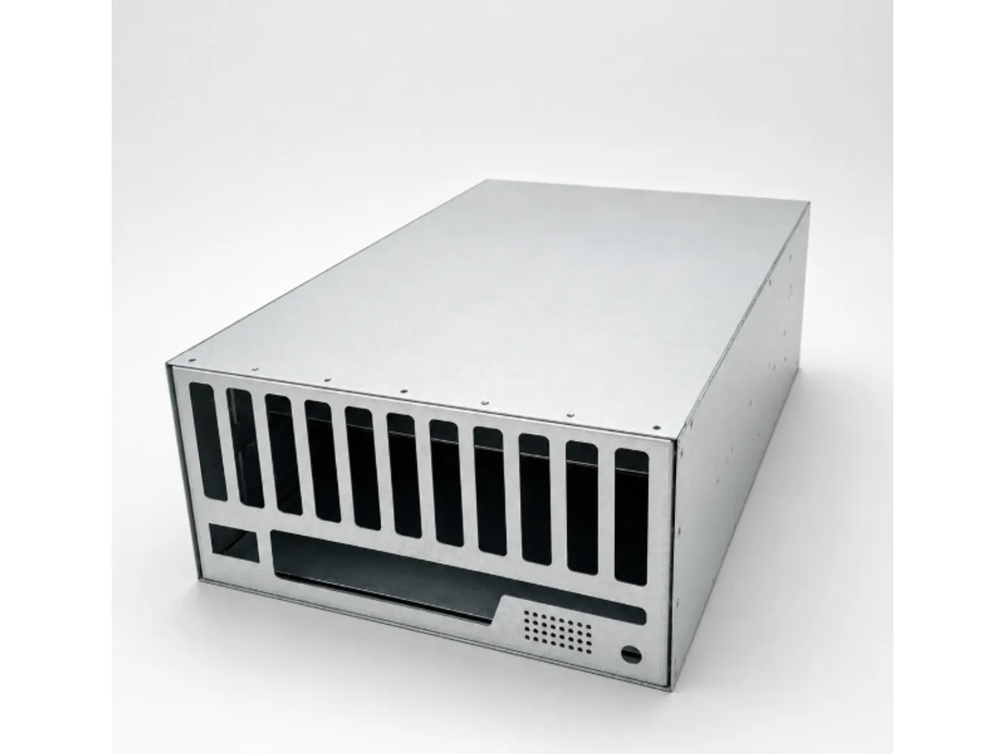
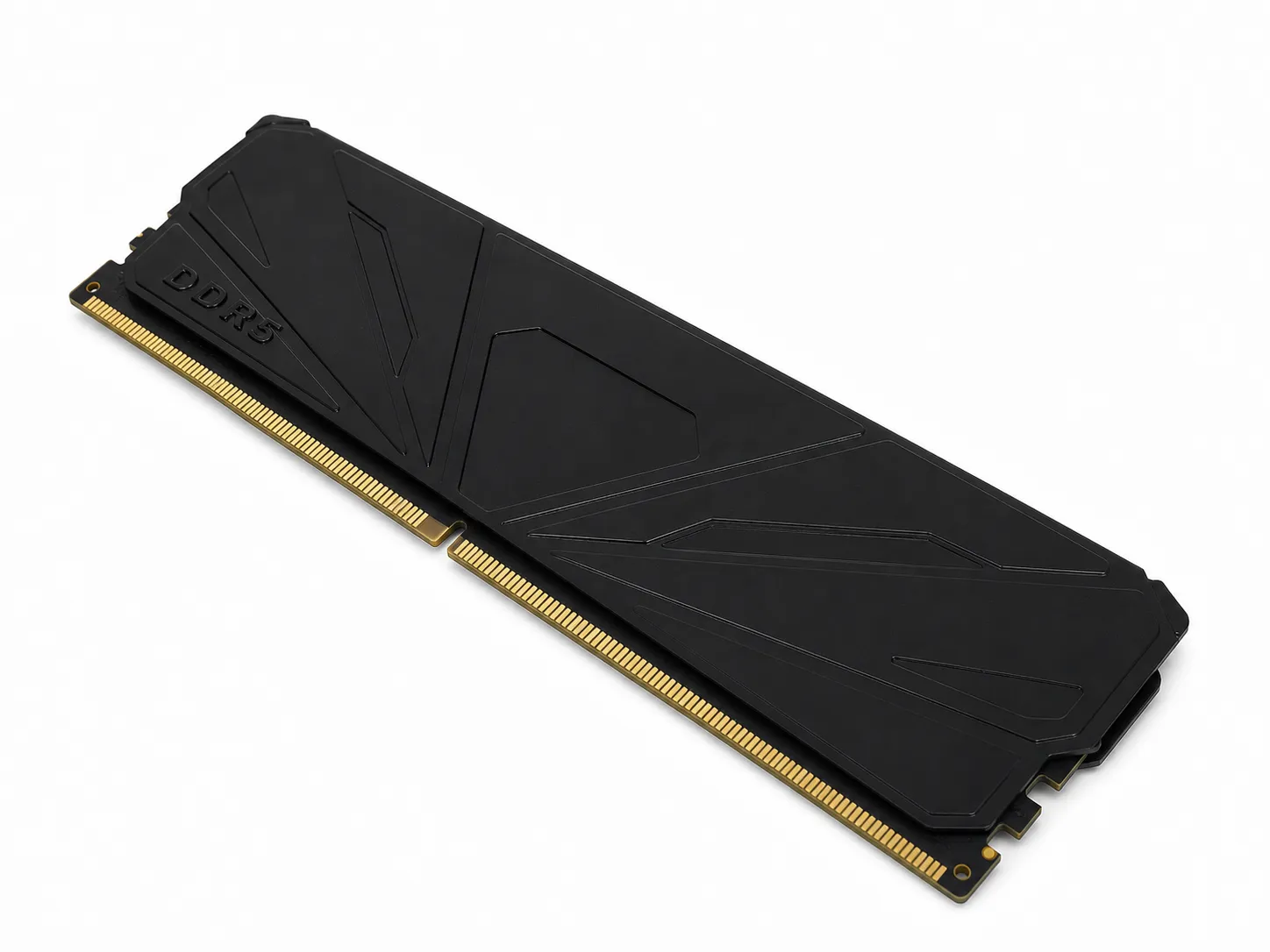
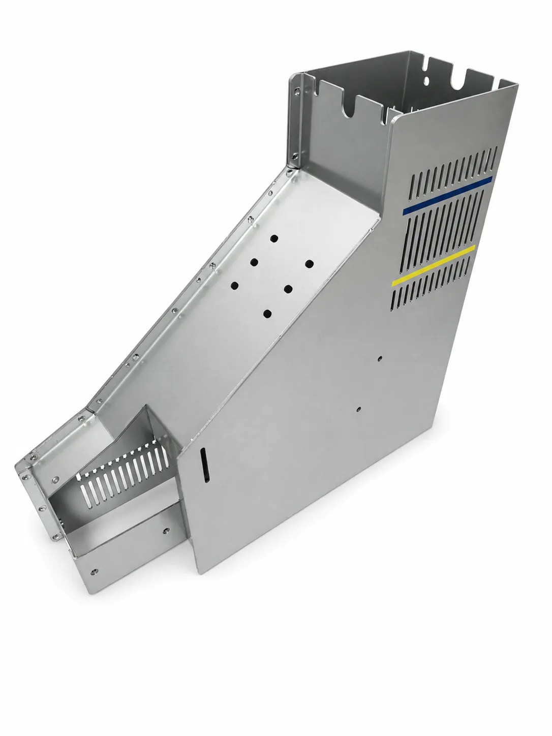
Representative product image — not a process record
Anonymized route example
Sheet metal enclosure components
A representative route may combine hole-making, formed features, threads and installed hardware before assembly checks.
01 Punching and countersinking
02 Trimming and secondary punching
03 Tapping
04 Hemming, bending and forming
05 Rivet installation and press riveting
06 Assembly and inspection
Typical checkpointsCheckpoints may include hole position, thread condition, formed geometry, hardware seating and final fit.
Representative production route. Actual steps, controls and external processes depend on the drawing and approved project plan.
Run T0, T1, T2 and additional trials until forming, dimension and appearance are stable.
T0 checks whether the part can be formed.
T1 corrects dimensions, burr, springback and appearance issues.
T2 verifies near-production stability.
Continue T3 or T4 if the part still needs tooling correction.
Each trial should include a trial report, dimensional report, issue photos, repair plan and next-trial schedule.
Tool trial reportDimensional reportIssue photosTool modification plan
10
Pilot Run
Run a small batch, often 300, 500 or 1000 pieces depending on the part, to validate production readiness.
Check dimensional stability, continuous press capability and cycle time.
Monitor burr change, material utilization, yield and operator work instructions.
Validate inspection frequency and packaging method.
Confirm packaging and transportation do not deform or scratch the parts.
Pilot run reportYield dataPackaging validationUpdated work instructions
11
Customer Approval and PPAP
Submit production samples and approval documents before formal mass production.
Common documents include dimensional report, material report, surface treatment report and samples.
High-requirement projects may include control plan, process flow chart, PFMEA, gauge report, CPK/stability data, packaging specification and PPAP documents.
Approval scope should match customer requirements instead of adding unnecessary paperwork.
Approved production samplesDimensional reportControl planPPAP package if required
12
Mass Production and Continuous Quality Control
Run production according to controlled documents and keep quality feedback tied to tooling and process improvement.
Execute SOP work instructions, first-piece inspection, patrol inspection and last-piece inspection.
Maintain tool checks, equipment checks, lot traceability and nonconforming product isolation.
Use daily production reports, outgoing inspection, customer complaint handling and continuous improvement.
Mass production partsInspection recordsTraceability recordsCorrective actions
Process vocabulary
Manufacturing terms buyers may see during RFQ and tooling review
metal stamping DFM reviewcustom metal stamping production processstamping die development processT0 T1 T2 tool trialpilot run for stamped metal partsPPAP for metal stamping partsmass production quality control for stamped parts
RFQ-ready capability
Have a part to quote?
Send drawings, material, thickness, finish and target quantity for review.