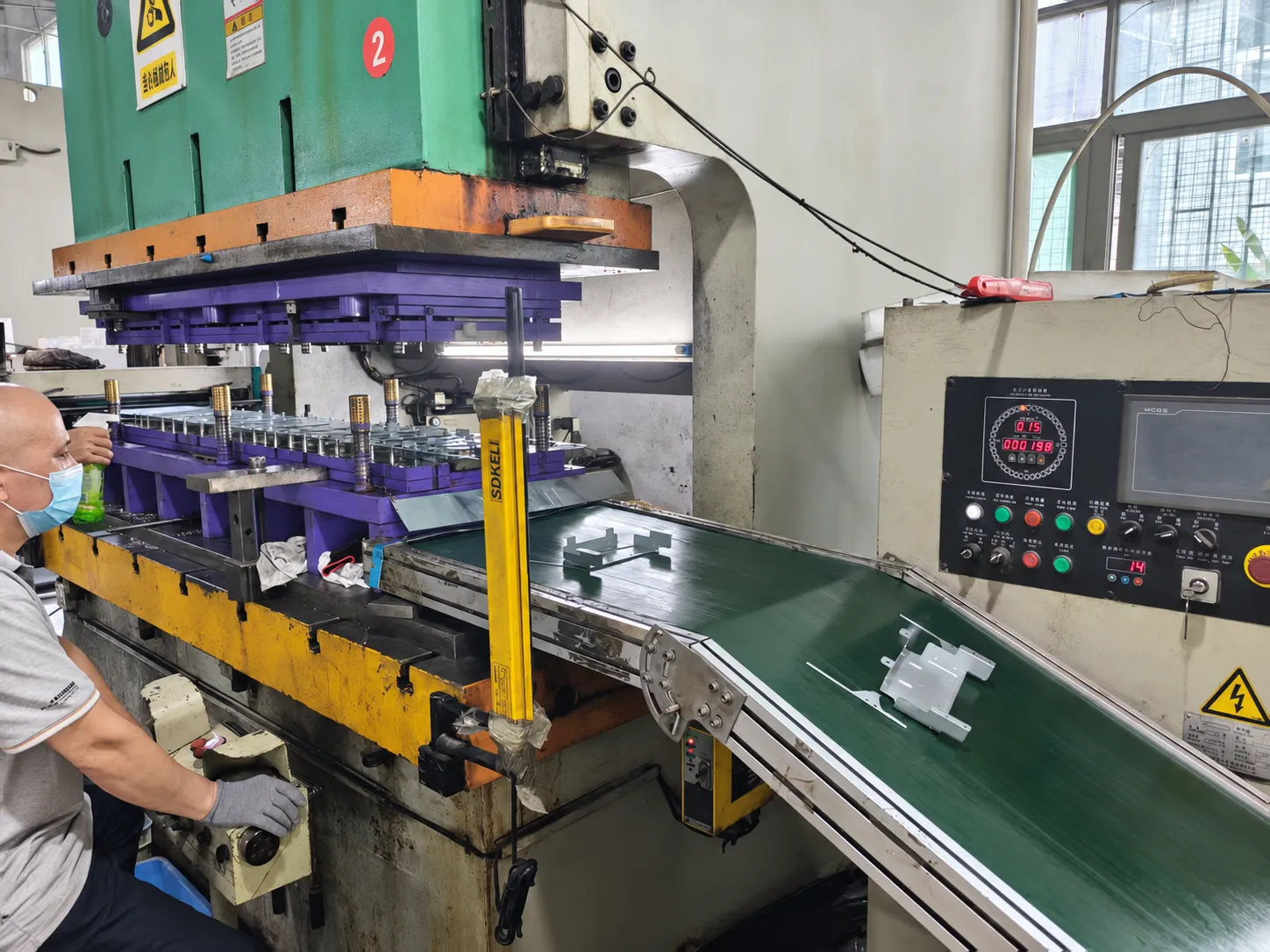
The useful way to read a process plan is to follow the part: what enters each operation, what changes, and what evidence allows the next operation to begin. This guide follows that production sequence.
It describes a typical cold-stamping route, not one mandatory sequence for every part. Sheet-fed blanks can bypass coil equipment; drawing, trimming and piercing may occur in a different order. Detailed defect diagnosis is covered in the companion troubleshooting guide.
1. Confirm the drawing and production route
Start with the drawing revision, material and condition, thickness, required features, finish and quantity. Identify the surfaces and dimensions that matter for assembly, along with the required measurement state. These inputs determine which features must survive every later step.
Engineering then chooses the operation order and tooling arrangement. A progressive die advances connected strip through stations; separate dies work on individual blanks. Press force, working range, stroke, energy and tool access must suit the operation. A high nominal tonnage alone does not establish suitability.
2. Verify material, then uncoil and level it
Check the incoming material identification, thickness and surface against the agreed specification and retain batch traceability. Material that looks similar may have a different grade or condition and behave differently during cutting or forming.
For coil-fed work, the line unwinds the strip and levels it for stable feeding. Check strip condition and alignment before it reaches the die. Precut blanks or sheet-fed work use a different handling route and do not necessarily need these coil stages.
3. Feed the material and make the required cuts
The feeder advances material by the planned step. In progressive tooling, the strip and locating features keep successive cuts and forms related to one another; feeding errors can affect several features at once.
Piercing removes material to make holes; blanking separates a useful outline. The cut edge, hole location and remaining carrier must suit later operations. Cutting clearance affects edge condition and tool loading, so it is selected for the actual material and operation rather than copied as one universal thickness percentage. [1]
4. Form the required three-dimensional shape
Bending turns a flange, drawing pulls material into a cavity, and other forming operations create features such as ribs or raised areas. A part may need one forming operation or several stages to reach its required shape.
Check material flow and the features most affected by forming. In drawing, excessive restraint can contribute to splitting, while insufficient support can allow wrinkles; the workable balance depends on geometry, material and contact conditions. Trial parts establish the route and settings before repeated production. [2]
5. Trim, separate and size where needed
A drawn part may need trimming after forming; a progressive-die part is separated from its carrier at the planned station. Holes can be pierced before or after forming depending on their required final position and tool access.
Sizing or restriking may be included when the agreed route needs it. Recheck cut edges, final hole positions and shape after these operations. Do not assume a dimension accepted on an intermediate blank will remain acceptable on the finished part.
6. Deburr, clean and finish to the specification
Remove or control burrs where required, then clean the parts for the next operation. Edge treatment must protect function: changing an edge can also affect a small hole, a fit or an electrical-contact area.
Plating, coating or other specified finishing enters the route in its agreed position. Confirm masking, contact areas and dimensions that must be checked after finishing. Some parts need no coating, so this stage should follow the drawing rather than a generic checklist.
7. Inspect the completed parts and pack them
Quality checks start earlier: approve first-off parts after setup and monitor critical features during the run. Final inspection checks the condition actually being delivered, including features affected by finishing, handling or assembly.
Verify the required records and batch identification, then use packaging suited to the part. Thin flanges may need support; finished surfaces may need separation. Packing should preserve the accepted shape and surface during handling and transport.
Follow a bracket through one possible route
For a simple pierced and bent bracket, an illustrative route is: verify strip material → feed and pierce → blank or retain the carrier → bend → separate if still attached → deburr and clean → finish if specified → inspect and pack.
This is a planning example, not a record of a pictured part's actual production. Holes with demanding final-position requirements may need a different order. The route must explain how each important feature reaches its final condition, not merely list machine names.
Use defects as checkpoints, then investigate separately
The table below connects production stages with things worth watching. An unexpected result is a signal to contain affected work and investigate; it does not prove one cause. For symptom recognition, cause checks and corrective-trial verification, continue with the dedicated guide.
| Stage | Check | Why it matters |
|---|---|---|
| Material and feeding | Identification, thickness, surface and strip position | Keep the intended material and location consistent. |
| Cutting | Hole location, cut edge and burr direction | Protect later forming and final fit. |
| Forming and sizing | Cracks, wrinkles and unloaded shape | Confirm that geometry and material flow remain acceptable. |
| Secondary operations | Final dimensions, edges and finished surfaces | Later treatment can change an earlier accepted feature. |
| Inspection and packing | Required records, part support and separation | Deliver the accepted part without handling damage. |