Why dense hole arrays affect the sheet more than a single hole
During punching, the punch pushes the metal that will become the slug into the die. Local deformation develops near the hole edge before the material separates. A dense hole array concentrates many of these deformations in a small area; as holes move closer together, the remaining ligaments become more susceptible to the effects of adjacent punching. Worn cutting edges, unsuitable clearance or insufficient local support can make distortion worse.[1]
The ligaments between holes are narrow strips of metal that keep the perforated sheet connected. The perforated region and the surrounding solid border differ in stiffness and deformation. Once the sheet is unloaded, bending, waviness or twisting may restore equilibrium. This is one way to analyze distortion; the actual direction of warping also depends on the initial material condition, hole pattern, border and forces applied by the tooling. It cannot be inferred from punch travel alone.
A sheet that sits against the tooling under hold-down pressure is not necessarily flat as a finished part. Holding it down can temporarily restrict movement, while the sheet may still warp after release.[2] Check “flat inside the tooling,” “free shape after removal” and “shape after assembly” as separate conditions.
Start with the metal remaining between holes
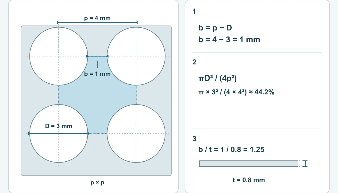
For a square array of equal-diameter round holes, let D be the hole diameter and p the distance between adjacent hole centers. The narrowest ligament width is then b = p − D. Sheet thickness t determines how much material that ligament contains through its thickness.
Example calculation: with hole diameter D = 3 mm, pitch p = 4 mm and sheet thickness t = 0.8 mm, b = 1 mm and b/t = 1.25. Excluding the solid outer border, the open-area percentage of an ideal infinite square array is πD²/(4p²), or approximately 44.2%. These values illustrate the geometry; they are not recommended hole spacing or a statement of manufacturing capability.
Two sheets with the same open-area percentage may behave differently. Round holes and slots, straight and staggered patterns, and uniform arrays and locally concentrated perforations leave ligaments running in different directions. The outer border width, solid areas around mounting holes and distance from the array to bend lines also matter. Open-area percentage describes how much area has been removed, but cannot by itself predict how much the sheet will warp after punching.
For drawing review, show how the complete hole array relates to the part outline, bends and mounting points, as well as the material, sheet thickness and hole diameter. The stamping DFM guide can help clarify the difference between clear spacing between holes and center-to-center pitch.
Slightly convex tooling: identify the raised surface
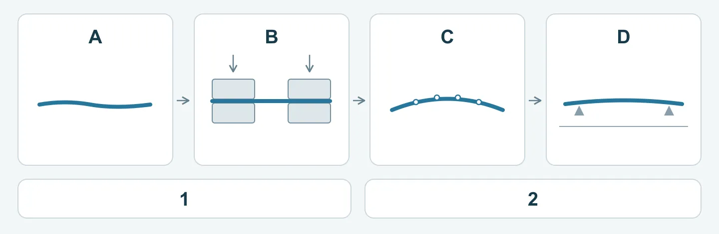
“Slightly convex” describes only part of the geometry. Changes to the punch cutting face, die support surface and hold-down face act in different ways. When discussing a solution, first identify the raised feature in a section view and establish when it contacts the sheet.
A shaped punch face changes the cutting sequence
A punch face with variations in height lets different areas contact and cut into the sheet at different points in the stroke. This changes how punching load is distributed over the stroke and may also change the slug shape. A convex punch face alone does not establish that the sheet will be flatter.[3]
Specific face designs can also affect the direction of material flow. Wilson’s JK Shear, for example, is designed to encourage flow toward the hole and slug, reducing the deformation transmitted to the surrounding sheet.[4] This mechanism must be tied to the particular face geometry; it should not be treated as an effect shared by every convex, angled or radiused punch.
Piercing and blanking also need to be distinguished. When perforations are pierced, the sheet containing the holes is normally retained and the small pieces cut out are scrap. If the cut-out piece is the finished part, an approach that permits slug deformation needs to be reassessed.[3]
A die support surface and matching hold-down face apply counter-bending
Another type of tooling changes where the sheet is supported and pressed. A raised die support surface works with a corresponding hold-down or stripper face to bend the sheet opposite to its existing warping tendency before and after separation.[2] This acts on the forces applied to the sheet and should be distinguished from the shear-height variation on a punch face.
The compensation must match the existing warping tendency. Too little rise may have insufficient effect; too much may introduce reverse distortion, impressions or changes at the hole edge. Confirm the contact regions, hold-down travel, punch penetration and die support together, then examine the final part after the trial. A particular rise or angle is not a universal answer.
Slightly convex tooling may aim to reduce or compensate for distortion, or to adjust material flow and force distribution. Describing it as “completely eliminating internal stress” goes beyond what these structures alone demonstrate. A special cutting edge does not automatically make a process fineblanking. For processes involving strong blank holding and counterpressure, see the fineblanking die structure guide.
Find where distortion begins before modifying the tooling
The most useful diagnostic information is the operation after which the part first shows a clear change in shape. Trying to infer a cutting-edge problem directly from the final part can wrongly attribute incoming-material, outline-cutting or later-operation effects to the piercing punch.
| Inspection stage | Shapes and effects to compare | How the findings guide the next step |
|---|---|---|
| Before punching | Waviness and bending direction in incoming sheet or blanks, material batch and orientation | Separate the initial shape from distortion introduced by processing |
| After a small number of holes and after the complete array | Changes in the perforated region, border and different directions | Determine whether distortion accumulates as the hole array expands |
| After hold-down and stripping | With the machine safely stopped, examine support and hold-down contact; measure the free shape after removal | Separate the constrained shape from the shape after unloading |
| After outline cutting, bending or post-processing | Relative changes in the final outline, mounting points and hole array | Avoid attributing later-operation changes to punching |
Keep consistent orientation marks and measurement locations on the same part through each stage. If the sheet is acceptable after perforating but changes clearly after outline cutting, examine the outline-cutting operation and the change in border restraint. If warping appears only after stripping, first examine hold-down, stripping and local support. The stamping defects troubleshooting guide provides further methods for locating defects by operation.
Stabilize the basic conditions before comparing special tooling
Assessing special tooling requires repeatable basic conditions. If cutting edges are dull, die heights are inconsistent or slug evacuation is unstable, changing only a raised feature makes it difficult to identify the true cause of differences between trials.
First check cutting-edge condition, actual punching clearance, punch-to-die alignment, and contact at the support and stripper surfaces; then check the material batch and lubrication. Clearance should suit the material and thickness. Simply reducing it may increase tool loads and heat, so “smaller clearance means flatter parts” should not be used as an adjustment rule.[1]
Punching order also deserves comparison alongside tool geometry. Staggering the impacts on neighboring holes, completing the array in groups, or arranging cluster punches to contact the sheet at different times are possible trial approaches.[1][4] The number of holes punched per stroke must account for hole layout, ligaments, load and cycle time. More holes in one stroke is not always better.
If the basic conditions are sound but repeatable warping remains, compare options such as a slightly raised support surface, a specific punch-face geometry or a subsequent leveling operation. Leveling also requires checks for its effects on hole shape and assembly, beyond the visible sheet surface.
How to verify that a tooling trial improves the final part
A controlled tooling trial starts with comparable results. Keep the material grade, batch, sheet thickness, blank orientation, hole array, outline, cutting-edge condition, lubrication and measurement method as consistent as possible. If cutting edges, hold-down, punching order and material are all changed together, the result may improve without revealing which change caused the improvement.
Record the current setup first, then change one principal factor. Retain several samples from each group and record changes over consecutive production. Set sample quantities according to part risk and production arrangements; one flat sample does not demonstrate stable batch performance.
| Comparison item | Recommended records |
|---|---|
| Sheet shape | Free shape after removal, shape after the final operation, measurement surface and support locations |
| Holes and assembly | Hole diameter, shape, position and pitch; mounting points and their relationship to mating components |
| Hole edges and surfaces | Burr direction and height, impressions and scratches; requirements for subsequent coatings or contact areas |
| Tool operation | Punching load or available machine records, stripping, slug evacuation, unusual sounds and wear |
| Production performance | Acceptance rate against the same requirements, cycle time, and the need for subsequent leveling or rework |
“Flatness” also requires an agreed measurement method. Forcing a thin sheet down with clamps measures its clamped condition. Placing it on a surface plate and measuring the largest gap can support process comparisons, but that result alone is not a complete inspection of the drawing’s flatness requirement. Engineering and quality teams should agree on the free or constrained state, measured surface, support method, measurement points and acceptance criteria. They should also distinguish surface flatness from the relative heights of mounting points. See the stamping tolerances guide for communicating finished-part condition and tolerances.
A solution is worth adopting if it consistently meets the final requirements. If a flatter sheet comes with changes in hole shape, surface impressions or a significant reduction in tool life, continue adjusting the setup or compare other approaches.
Information needed for quotation and drawing review
Buyers do not need to specify tool rise, clearance or hold-down force first. It is more useful to explain how the part will be used: must the perforated panel lie flat in its free state, or fit flush after installation? Which areas contact mating parts, cables or sealing surfaces? Are there bends, welds or later surface treatments near the hole array?
When sending drawings, include the material and sheet thickness, complete hole pattern and outline, mounting locations, expected quantity and the issue of greatest concern. If samples are available, add photographs before and after punching and in the final condition, identifying each face, the warping direction and measurement conditions.
If the material, hole spacing or flatness requirement is still undecided, send a sketch or photographs first. Mark the areas that need to fit flush, provide ventilation or align during assembly, and identify the open questions. This helps us understand the requirements, discuss options and prepare a quotation.