A conventionally blanked edge can contain rollover, a burnished zone, a fracture zone and a burr. If it engages teeth, forms a close fit or slides against another component, correct outline dimensions alone may be insufficient. Check the actual contact height, edge taper and flatness after the part is released.
Possible routes include preliminary blanking followed by shaving, fineblanking with blankholding and counterpressure, or coordinated trimming from opposite directions. Each changes how the material separates and requires a different combination of equipment, tooling and operations. Start with the functional surfaces and acceptance requirements.
What does each structure control?
Three questions distinguish these structures: how stock allowance is distributed, how material is restrained during separation, and how the upper and lower tools work together. Multi-stage shaving distributes stock removal between operations; fineblanking establishes blankholding and counterpressure during separation; opposed trimming uses tool motion from different directions to process the contours.
These features can coexist in one process. A fineblanked part may still require local shaving, and opposed trimming can incorporate blankholding and counterpressure. Identify the principal part problem, then decide which operation and support location should address it.
Assess the cut section, dimensions and flatness
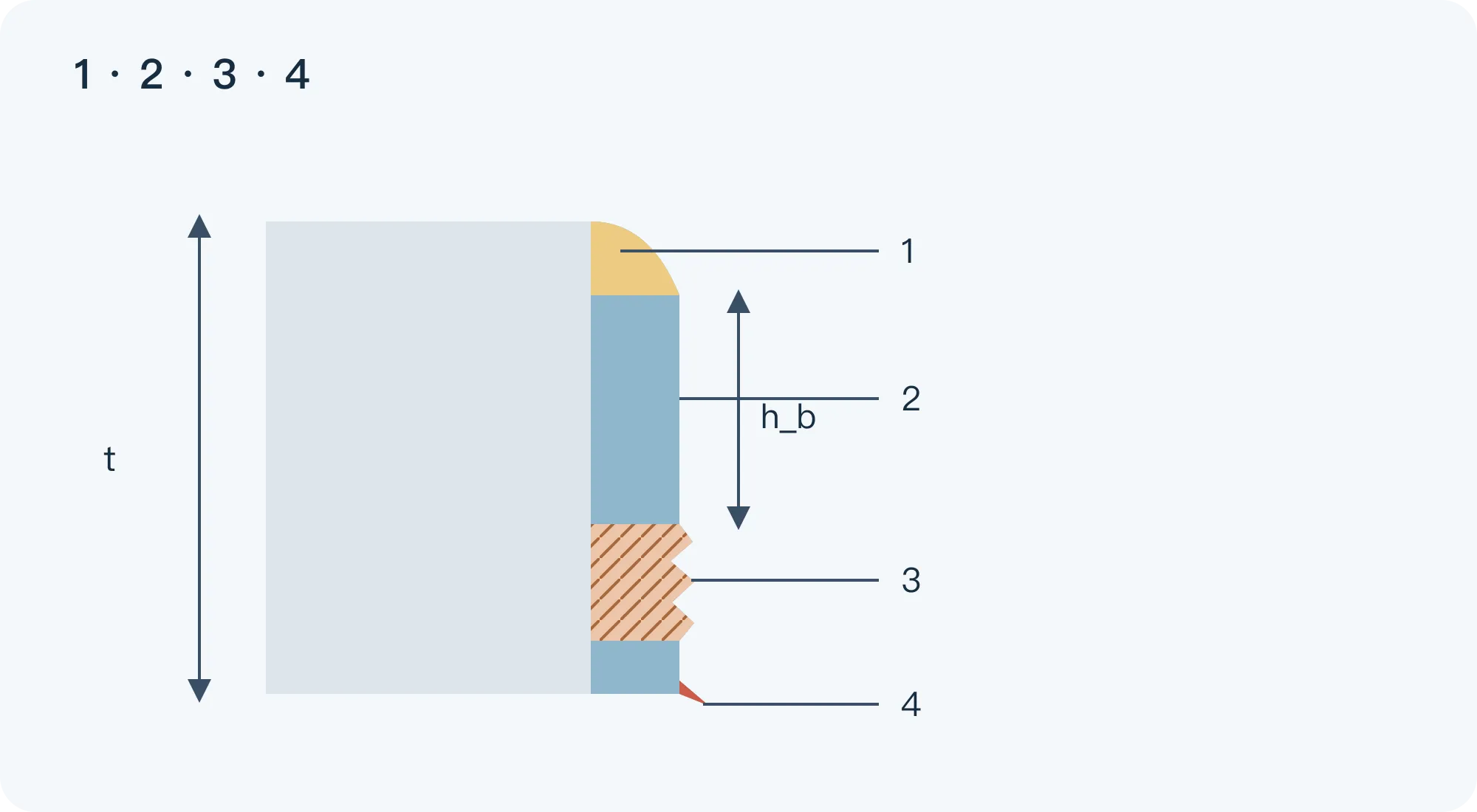
A larger burnished zone generally provides a more continuous contact edge, but its percentage cannot replace complete acceptance checks. Rollover reduces effective contact height; fracture affects edge form and fit; burr size and direction can affect assembly, handling or movement. Check taper, local cracks and part flatness separately. [1][2]
A toothed locking plate needs checks of tooth-flank engagement height and profile. A shaft-fitting hole needs checks of wall form, diameter and the agreed go-gauge condition. Thin rings and washers may be sensitive to distortion after release. A correct outline does not eliminate these functional errors.
Agree on measurement position and direction before reporting the burnished-zone percentage. If its height along the thickness direction at a section is h_b and original thickness is t, the local proportion is h_b/t × 100%. Calculation example: t = 2.00 mm and h_b = 1.60 mm give 80%. Inspect tooth roots, sharp corners, straight edges and hole edges separately, using their actual contact requirements.
Multi-stage shaving: leave stock, then finish the functional edge
One route forms a near-final contour, then removes a thin layer of reserved stock. The subsequent operation is commonly called shaving. It requires a defined allowance, locating relationship and final cutting edge rather than repeated blanking to the same size. [3]
Stock distribution is the first design issue. Preliminary blanking determines where shaving begins; shaving determines which functional edge remains. Fracture, contour error and distortion from the first operation become input conditions for the next. Define four items:
- Condition after preliminary blanking: record dimensions, rollover, fracture and existing distortion.
- Stock to remove: distinguish the allowance direction for outer contours and holes, and check its uniformity along complex shapes.
- Locating and support: guidance, clamping or support changes can turn thin-layer removal into local gouging and alter hole position, outline or flatness.
- Chip removal: include shaving-chip discharge, stripping and lubrication in the design before chips jam.
Arrange the number of shaving operations together with removal per pass, thickness and cutting-edge geometry. In thick-sheet shaving, penetration and cutting portions alter local compression and crack formation, affecting how much finishing one operation can complete. [3] Each extra operation also adds locating, chip-handling and maintenance issues; confirm that it improves the edge being retained.
Evaluate this route when the existing production arrangement can accommodate a shaving station or only selected hole walls, tooth flanks or contours need improvement. Include additional stations or handling, allowance control, locating, chips and maintenance. Simplicity and cost depend on the complete sequence.
Fineblanking with strong blankholding: control flow in the shear zone
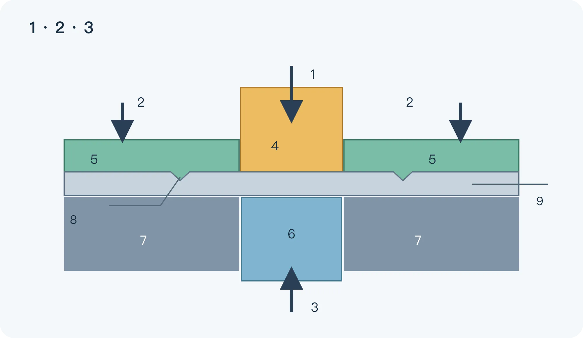
Fineblanking with strong blankholding restrains the surrounding material while supporting the separating part with counterpressure from the opposite side. The counterpunch must provide support during cutting, with force and travel controlled for the process. An ejector that acts only after separation principally addresses part removal. [1][4]
The punch separates the material; the blankholder and V-ring restrain the surroundings; the counterpunch supports the separating part. Together they affect stress and flow in the shear zone, helping delay fracture and improve the cut section. [1][4] Increasing restraint and counterpressure also requires checks of tool loading, impressions, stripping and equipment capability.
Assess whether the equipment can control these actions and their sequence, not just its nominal tonnage. Tool rigidity, guidance, relative position under load and travel control must work together. An acceptable static clearance does not establish that clearance remains acceptable everywhere during cutting.
The investment should be justified by specific operations it removes. If tooth flanks or fitting contours meet requirements in the die, their subsequent machining may be reduced. If deburring, flattening or precision finishing remain necessary, retain those operations and costs in the comparison. [5]
Opposed trimming: identify the cutting edges before coordinating motion
First identify which contour each cutting edge processes, which region is the finished part, and how the part and scrap are supported and removed. Only then can cutting directions, entry and exit surfaces, supports and stripping sequence be arranged.
Cutting different contours in opposite directions differs from cutting the same contour from both sides. Staged counter-blanking also requires control of the two penetration depths and tool dimensions. [6] Draw these relationships explicitly before setting local clearances and travel.
Show the cutting sequence and closed positions: when blankholding starts, when each edge contacts material, permitted penetration, when support ends and whether scrap has cleared after return. For oppositely directed hole and outline cutting, identify entry, exit and permitted burr direction for each edge.
Assess flatness from the loading distribution over the whole part. Asymmetric contours, different contact times, die-set deflection and wear can leave local distortion. Check support during cutting and measure the released part. Residual warping may require changes in motion order, support area or a separate flattening operation.
V-ring position determines where restraint is established
The V-shaped projection on the blankholder is commonly called a V-ring. Its penetration restrains material around the contour and limits flow near the cut, while the main cutting edge separates the material. Its action must match the blankholding force and cutting location.
Design V-ring height, shape and distance from the contour together with material, thickness, local geometry and holding conditions. At corners, examine the combined influence of ring position and die-entry geometry on rollover. [7] During trials, keep other conditions constant and compare sections and impressions before adjusting local ring positions.
Why clearance cannot simply be reduced indefinitely
Clearance must meet both cut-edge requirements and tool operating conditions. Reducing it changes stress and flow and may increase punch loading. [1][2] Evaluate edge quality, tool positions under load and return-stroke stripping together.
For circular tools, let die diameter be D_d and punch diameter D_p. One-side clearance is c = (D_d − D_p)/2. Calculation example: D_d = 10.04 mm and D_p = 10.00 mm give c = 0.02 mm; at t = 2.00 mm this is 1% of thickness. This defines and illustrates clearance, not a recommended setting. Irregular contours require checks of local normal clearance.
Fracture-zone changes and tool-load changes need not track one another as clearance decreases. Once the edge meets requirements, check whether further loading causes pickup, wear or difficult stripping. Zero or negative clearance also changes exit deformation; measure rollover and exit form separately. [1][2]
Determine travel control during design for zero or negative clearance. Punch and die contours may contact, so check permitted penetration, die-entry geometry and loaded tool deformation. If penetration stops early and a later station removes the remaining connection, specify locating and separation in both operations. [2] Reconfirm the operating range for different thicknesses and material conditions.
Compare the three routes on the same basis
Compare the edges that need improvement and the available operation sequence before comparing equipment and die investment. The table uses the same design dimensions for all three routes.
| Comparison | Multi-stage blanking and shaving | Dedicated fineblanking | Coordinated opposed trimming |
|---|---|---|---|
| Process approach | Form the contour, then remove reserved edge stock | Control the shear zone with cutting, blankholding and counterpressure | Process the contours through upper and lower cutting motions |
| First checks | Allowance, locating, support and chips | Force and motion control, clearance, V-ring and rigidity | Contour sequence, closed positions, support and scrap |
| Needs worth evaluating | Selected functional edges need improvement and shaving fits the sequence | Several contours need continuous cut sections and demand justifies tooling and equipment | Geometry and stations suit opposed cutting; section and form control need validation |
| Trial focus | Sections, dimensions and locating after each pass | Critical contours, tool loading and stripping | Edge contact order, scrap separation and released flatness |
| Include in cost | Stations, locating, chips, handling and maintenance | Tooling, machine time, material use, regrinding and secondary work | Guidance, linkage, setup, scrap and maintenance |
Compare the same final dimensions, cut-section requirements, deburring and flatness state, inspection scope and delivery quantity. A cheaper die with substantial secondary work can cost more overall than a more expensive die that removes operations. Conversely, low demand or likely design changes may prevent recovery of complex tooling costs.
What must trials demonstrate before production release?
Trials should demonstrate continuous production of accepted parts, beyond one visually bright sample. For the same material grade, condition and thickness range, record lubrication, speed, blankholding, counterpressure, tool condition and measurement method, then inspect:
- Critical cut sections: rollover, burnish, fracture, burr, taper and cracks at straight edges, corners, tooth roots and holes.
- Dimensions and form: hole size, contour, relative positions and flatness; state whether measurement is free-state or under agreed clamping.
- Motion and scrap: smooth stripping, retained scrap, abnormal tool contact and load changes.
- Continuous production and maintenance: sample trends, pickup, edge wear, dimensions and sections before and after regrinding, and actual cost per accepted part.
Include maintenance in trials. Coating hardness, toughness, adhesion and friction must work together; performance also depends on workpiece material, punch contour and loading. [8] Hold the workpiece and conditions constant and record accepted-part count, pickup, wear location and regrinding intervals to compare maintenance cost per accepted part.
Start the discussion with the part's function
Send a drawing, sketch or photograph and identify edges used for engagement, sliding, contact or close fits. State material, thickness, expected quantity and current burr, cut-section or warping problems. Mark unresolved tolerances and inspection requirements as open.
These details allow a comparison of additional shaving stations, fineblanking with blankholding and counterpressure, or opposed trimming, with trial results tied to the final use requirements.
- Suzuki Y., Shiratori T., Yang M., Murakawa M. Elucidation of Shearing Mechanism of Finish-type FB and Extrusion-type FB for Thin Foil of JIS SUS304 by Numerical and EBSD Analyses. Materials, 2019, 12(13):2143
- Suzuki Y., Yang M., Murakawa M. Optimum Clearance in the Microblanking of Thin Foil of Austenitic Stainless Steel JIS SUS304 Studied from Shear Cut Surface and Punch Load. Materials, 2020, 13(3):678
- Sontamino A., Thipprakmas S. Modified shaving die for shaving thick sheet metal. The International Journal of Advanced Manufacturing Technology, 2023, 128:2469–2481 (public abstract)
- Hu C., Shi Y., Liu F. Research on Precision Blanking Process Design of Micro Gear Based on Piezoelectric Actuator. Micromachines, 2021, 12(2):200
- Feintool, Fineblanking
- Thipprakmas S. Parameter Design for the Counter-Blanking Process Using the Finite Element Method and the Taguchi Approach. Key Engineering Materials, 2010, 443:134–139 (public abstract)
- Kim J. D. An Experimental Study on the Effect of Die Chamfer Shape and V-Ring Position on Die Roll Height in the Fine Blanking of a Special Part with Various Corner Shapes. Applied Mechanics and Materials, 2013, 365–366:569–575 (public abstract)
- Daniel J. et al. Comparison of Lifetime of the PVD Coatings in Laboratory Dynamic Impact Test and Industrial Fine Blanking Process. Materials, 2020, 13(9):2154