A crack is an observation; 'not enough lubricant' is a hypothesis that still needs evidence. Keeping those two things separate helps avoid adjustments that hide one symptom while creating another.
This guide concerns common cold-stamping problems and an evidence-led investigation. It does not prescribe machine settings or cover every fracture mechanism. The production sequence is explained in the companion process guide.
Start with the symptom and the first affected operation
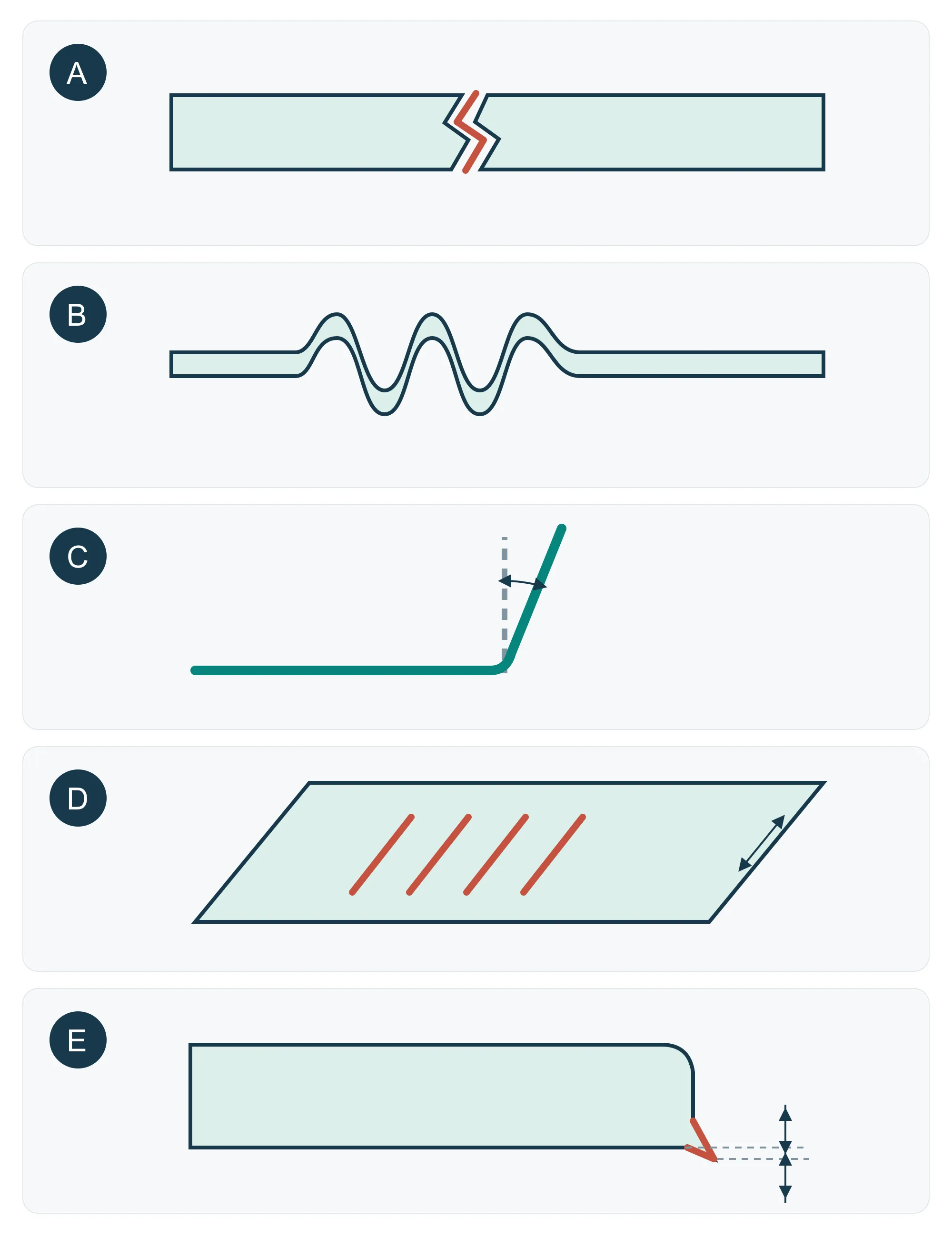
Keep an affected sample and a recent accepted reference. Record the drawing revision, material batch, operation, time of first observation and how the part was supported during measurement. Photograph the whole part and the marked defect area.
Separate potentially affected work while its extent is assessed. Inspection or tool access must follow the site's isolation procedures; a photograph cannot establish whether a machine is safely stopped.
- Mark which face, edge or radius is affected and whether the pattern repeats.
- Compare parts before and after the suspected operation, including handling and packing.
- Use the diagram to name the symptom; use the checks below to investigate its cause.
A — Cracks: locate the starting point
Look for the start of the crack, not only its widest opening. A sidewall or radius split with visible thinning calls for different checks from a crack that starts at a sheared edge. Edge condition and later stretching can interact. [1][2]
Compare local thickness, material grade and condition, blank position and nearby cut edges with accepted parts. For a drawn region, review the path by which material enters it, including lubrication and restraint. For an edge-origin crack, inspect the earlier cut before changing the forming stage.
Engineering may review the cutting condition, radius, material flow or operation sequence according to the evidence. A trial must check that the crack is removed without introducing wrinkles, excessive thinning or a new fit problem.
B — Wrinkles: check support and material flow
Wrinkles are waves associated with compressive material flow or insufficient support. Record where they first appear: the flange, sidewall or a locally unsupported region. Also check whether they are present before forming or introduced by later handling. [2]
Compare blank placement, contact and support, lubrication coverage and the way material draws in around the part. An uneven pattern can help locate an imbalance, but appearance alone cannot identify the setting to change.
More restraint can reduce wrinkling while increasing stretching and the risk of splitting. After a reviewed trial, check the complete shape, local thickness and crack-prone regions as well as the original waves.
C — Springback: compare the same measurement state
Springback is elastic recovery when forming loads and constraints are removed. It can change a bend angle, curve a wall or twist a part. Material properties, work hardening, geometry and the loading history influence the result; extra press force is not a universal correction. [3]
Measure accepted and affected parts from the same datums, with the same supports and in the state required by the drawing. Pressing a flexible part flat for inspection can hide a free-state problem. If it changed after trimming, include that operation in the investigation.
Compare material batches and verified tool conditions before reviewing compensation or sizing. Recheck hole positions, assembly fit and the required free or constrained condition after any change.
D — Scoring and galling: follow the contact path
Scoring is a surface groove; galling involves adhesion and material transfer at sliding contact. They can occur together. A line on a part can also come from feed equipment, a conveyor or packaging, so locate the first stage where it appears. [4]
Compare the direction and repeated position of marks with contact surfaces. Under safe inspection conditions, check for adhered material, particles, damaged surfaces and inconsistent lubrication. Do not label every scratch as a rough die.
Restore the verified cleaning or lubrication condition where evidence supports it; tooling repair needs an engineering assessment. Inspect several subsequent parts and the affected contact area to see whether the marks recur, and confirm that surface and dimensions still meet the requirements.
E — Burrs: inspect the cut edge, not only its height
A burr is a raised lip associated with a cut edge, usually on the exit side. Its location and size can vary around the contour. Tool wear or damage, clearance, alignment and material variation can contribute. Burr height alone does not describe all cut-edge damage or later edge formability. [1]
Mark the worst locations and compare both sides and the cut-face appearance with a known-good part. Check the agreed measurement method and the material thickness before reviewing the cutting edge and alignment. A burr on one section of the contour needs localized investigation.
Do not apply one clearance percentage or burr limit to every part. After an approved correction or deburring operation, recheck hole size, remaining edge geometry and areas that affect fitting, wiring or contact. Removing a sharp lip does not repair a crack underneath it.
Use the pattern across parts to narrow the checks
A sudden change after a material or setup change suggests checking that transition first. A trend that develops during a run makes wear, buildup and changing process conditions worth checking. Neither pattern proves the cause.
The same mark at the same location across parts points toward a repeated operation or contact. Marks appearing only after transfer or packing require a handling check. Keep batch and sequence information so these comparisons are made between equivalent parts.
Verify a correction before releasing affected work
Define the acceptance criteria and the trial conditions before changing a reviewed factor. Keep the material, measurement method and other relevant conditions comparable; record what changed and the trial sequence. Only qualified personnel should adjust or inspect tooling under the required safe procedures.
Recheck the original defect and other features the change can influence. Then monitor repeated parts for recurrence using the agreed control plan. One improved sample does not establish stable production or determine the full extent of an affected batch.
Record the decision, responsible reviewer and disposition of affected parts. Rework, sorting or release must follow the agreed requirements; do not silently widen a tolerance to pass a trial.
Example: a better angle can still be a failed part
Teaching example: a drawing requires a 90° ± 1° angle and a 10.00 ± 0.10 mm hole. After a corrective trial, the angle measures 90.5°, but the hole measures 10.16 mm, using the agreed measurement conditions.
The angle is within 89°–91°, while the hole exceeds its 10.10 mm upper limit. That trial part fails the hole requirement, even though the original angle problem improved. Continue the investigation and verify both features together. These are illustrative values, not measured factory results.
| Observed symptom | Possible contributors | What to check |
|---|---|---|
| A — Splitting | Restricted draw-in, tight radii, local thinning, damaged cut edges or unsuitable material condition | Locate the start of the crack; compare local thickness, edge quality, material lot and lubrication with an accepted sample. |
| B — Wrinkling | Compressive flow with insufficient support or restraint; blank shape and uneven draw-in | Map where waves start; check blank position, holder contact and draw-in around the perimeter before changing restraint. |
| C — Springback | Elastic recovery affected by strength, elastic modulus, bend radius relative to sheet thickness, work hardening and forming history | Measure released angle or profile using the agreed supports; compare material lots and tool setup before assessing compensation or restrike. |
| D — Scoring / galling | Transferred material, particles, tool-surface damage or unsuitable lubrication | Compare the mark direction with sliding contact; inspect tool pickup and cleaning/lubrication condition. |
| E — Excessive burr | Cutting-edge wear or damage, clearance or alignment variation, material/thickness variation | Check burr height and cut-face condition around the outline; inspect cutting edges and clearance, and identify assembly-sensitive edges. |