A mounting screw will not fit through a stamped bracket, even though the hole diameter passed inspection. Tightening the diameter tolerance will not correct a misplaced hole center. First, identify which dimension or position is causing the problem and which operation affects it.
This guide walks through the checks: distinguish tool clearance from part tolerance, calculate hole-position error, work out assembly clearance and interpret process capability data. The numerical examples use hypothetical design and process values.
Which dimensions on the drawing need individual control?
Start with the contact surfaces, supports and locating features used in assembly. Identify their size, position and shape requirements, then check whether those features are produced in one cutting operation or also go through forming. This helps determine which dimensions and positions need to be checked after forming.
For example, 50.00 ±0.10 mm permits 49.90–50.10 mm, a total tolerance width of 0.20 mm. Those limits do not by themselves specify location or orientation; size/form relationships follow the chosen drawing standard. Name the standard and edition, and provide applicable general tolerances for dimensions without individual limits.
- Holes on one flat face: check both their diameters and their positions relative to the functional datums. A correct hole-to-hole distance does not guarantee a correct hole-to-edge distance.
- Features on opposite sides of a bend: check their final relative positions, because bend angle, bend radius and locating variation all affect the result.
- Seating surface or mating gap: decide whether function depends on free-state shape or the shape in the specified assembly. Put that state into the inspection requirement.
Why is punch-to-die clearance different from the hole tolerance?
The hole tolerance defines the permitted finished opening; punch-to-die clearance is the space between two cutting edges in the tool. MISUMI describes this clearance per side of the punch. Changing it affects shearing, edge quality and tool loading, but it does not directly specify a plus-or-minus tolerance on the finished hole.
For a concentric round punch and die, per-side clearance c = (D_die − D_punch) / 2. Suppose the sheet is 1.00 mm thick, the punch diameter is 6.00 mm and the tool designer selects c = 0.08 mm. The die opening is 6.00 + 2 × 0.08 = 6.16 mm. This example assumes a per-side clearance of 8% of the sheet thickness; it does not mean the finished hole has a tolerance of ±0.08 mm.
A conventionally pierced hole can have rollover at the entry, a burnished zone, a fracture zone and an exit burr. A caliper reading at the opening may not reveal what stops a locating pin from passing through the whole hole. If the pin will not fit, inspect the hole wall and burrs before deciding whether to change the diameter tolerance.
- Drawing: specify finished diameter limits, a separate location requirement and the burr or edge condition needed for the fit.
- Tool review: state whether clearance means per side or total, then assess material, thickness, alignment, edge condition and wear together.
- Acceptance: distinguish diameter measurement from a functional go-gauge check. If the hole wall determines the fit, assess whether the process needs shaving, fine blanking or a subsequent finishing operation.
Why can X and Y pass while the hole's position fails?
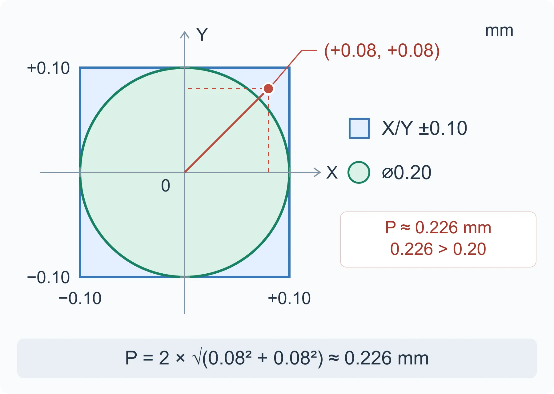
Independent X/Y tolerances define a rectangular region; a diametrical position tolerance defines a circular cross-section of the permitted zone. They are different geometric requirements. Check the drawing's datum system and tolerance-zone shape before deciding whether a measured hole location is acceptable.
Datum setup example: a sufficiently rigid rectangular mounting base can use three supports for primary datum A, two side locators for B and one end locator for C. This 3-2-1 arrangement illustrates how an inspection setup can reproduce assembly location. Flexible sheet may deform under contact, so support and restraint must match the specified inspection state.
Keep surface controls separate: flatness controls the surface's own form without a datum, while perpendicularity controls orientation to a datum. A flat mounting face can still be tilted. Use the chosen ASME or ISO GPS system consistently, including its size/form rules and modifiers.
Worked example: a hole center at +0.08 mm in both directions
Assume the measured center differs from the basic location by Δx = +0.08 mm and Δy = +0.08 mm. Both coordinates pass an individual ±0.10 mm limit. For the simplified two-dimensional circular zone, the diametrical error is P = 2 × √(Δx² + Δy²) ≈ 0.226 mm, which exceeds a ⌀0.20 mm position requirement.
The sketch compares those zones, not the physical hole diameter. This example assumes a fixed datum setup and an otherwise ideal hole axis; it excludes axis tilt, projected zones, material-condition bonus tolerance and datum shift. A real three-dimensional position check must evaluate the full requirement, not just one center point.
Why can a small bend-angle error cause an assembly problem?
For the same bend-angle error, a hole or mounting point moves farther if it is farther from the bend line. Springback is the material's elastic recovery after the forming load is removed. The final angle therefore depends on material properties, thickness variation, part geometry and forming conditions. Thicker or harder sheet does not automatically require a wider tolerance.
Illustrative geometry: take a rigid flange with a point 40 mm from an ideal bend axis. If the only error is a 1° rotation, the displacement perpendicular to the intended flange direction is 40 × sin(1°), approximately 0.70 mm.
You can also work backward from the assembly requirement. If that point may move only 0.20 mm perpendicular to its intended direction, allocating all of that movement to rotation gives an angle limit of arcsin(0.20 / 40) ≈ 0.286°. This leaves no allowance for variation in bend radius, thickness or locating position. If the final mounting position determines whether the part fits, specify and inspect that position directly.
- A hole becomes elongated after bending: first inspect the deformation near the bend. Moving the hole out of that region, adding appropriate relief or piercing/finishing after forming are options to review; tighter flat-blank dimensions alone will not remove the strain.
- The bend angle is within tolerance, but the mounting point is misplaced: check the datums and the full dimension chain, including the distance from the bend and the position of the bend itself.
How do you check a tolerance stack before tightening tolerances?
Calculate the limits of the assembly result, then allocate tolerances to the dimensions that contribute to it. For a simple clearance C = W − B, the minimum is W_min − B_max and the maximum is W_max − B_min. A nominal gap alone cannot show whether every acceptable pair will fit.
Design example in the finished condition: a slot width W is 20.00 ±0.10 mm and an insert width B is 19.70 ±0.10 mm. Nominal total clearance is 0.30 mm. Minimum clearance is 19.90 − 19.80 = 0.10 mm; maximum clearance is 20.10 − 19.60 = 0.50 mm. Total clearance is shared between the two sides according to how the insert locates.
Suppose the assembly needs at least 0.20 mm total clearance while the nominal difference remains 0.30 mm. In this worst-case calculation, which considers width only, the two values after the ± signs must add up to no more than 0.10 mm. Here are two ways to meet that requirement:
- Keep the nominal sizes and change both width tolerances to ±0.05 mm: minimum clearance becomes 19.95 − 19.75 = 0.20 mm and maximum becomes 20.05 − 19.65 = 0.40 mm. The tradeoff is tighter width control.
- Keep both tolerances at ±0.10 mm and reduce the insert nominal width to 19.60 mm: minimum clearance becomes 19.90 − 19.70 = 0.20 mm and maximum becomes 20.10 − 19.50 = 0.60 mm. The tradeoff is more possible play; confirm that maximum clearance is acceptable.
- Both calculations use finished widths only. Alignment, form, temperature and load effects still need to be assessed. Do not subtract coating thickness again if the limits already describe finished parts. Statistical tolerance analysis requires justified assumptions about the distributions and correlations of the contributing dimensions; it does not automatically replace a worst-case check.
Should you measure the part free, clamped or after finishing?
Measurement conditions are part of the acceptance requirements. A thin stamped part may change shape when pressed against a plate, clamped in a fixture or assembled with screws. Agree on those conditions before approving samples so that the buyer and supplier measure the part in the same state.
Finishing can also affect fit. Coatings can build on contact surfaces, while deburring or other processing can alter edges or shape. Specify whether dimensions apply before or after finishing, and review coating allowance by surface and process. When a dimension already specifies the finished condition, do not subtract the same coating allowance again.
- Free state: define supports and orientation; avoid a measuring force that unintentionally flattens the part.
- Restrained state: define locating points, clamping sequence and the agreed load or torque where relevant.
- Surface condition: state the required finishing stage and the burr or edge condition at inspection.
- Measurement environment: agree temperature or conditioning requirements when they materially affect the result.
What could an inspection note say?
An illustrative note could read: Inspect dimensions after deburring and the specified finishing. Check free-state flatness at the support locations and gravity direction shown on the inspection drawing, without a flattening load. Establish A, B and C as defined for the hole-pattern position check. Record drawing revision, inspection setup, method and results.
If fit must be checked with assembly screws tightened, make that a separate inspection item and specify locating points, tightening sequence and the required torque. A restrained flatness result must not be entered as evidence for the free-state requirement. KEYENCE's non-rigid-part guidance illustrates why gravity and restraint conditions belong in the specification.
Which inspection method can verify the requirement?
Choose a method that can measure the specified dimension, position or shape and assess it against the tolerance zone. Calipers can check some accessible dimensions, but they cannot by themselves verify hole-pattern position or surface flatness. Instrument resolution is not the same as measurement accuracy or uncertainty.
A useful first check is to measure the same part, remove it, locate it again and repeat the measurement. If reloading changes the result by an appreciable part of the tolerance band, investigate support, alignment, force and sampling before blaming the production process. Calibration alone does not show that the complete setup is suitable for this feature.
- Accessible dimensions: use a calibrated micrometer or caliper with suitable measuring contacts and force. More digits on the display do not necessarily mean lower measurement uncertainty.
- Hole fit: a simple plug gauge can check an agreed size or passage condition; it cannot by itself prove the hole pattern's position. A functional pattern gauge must simulate the applicable datum and drawing conditions.
- Hole position or profile: use an appropriate coordinate or optical method. Where the axis is controlled, sample enough of the hole depth to assess it; one circle at the entrance is not a complete axis check, as KEYENCE's measurement guide explains.
- Flatness or formed surfaces: sample the required area sufficiently and preserve its specified state. Agree the decision rule for results close to the acceptance limit.
How can a process have a good Cp but a poor Cpk?
Cp compares the process spread with the specification width; Cpk also reflects how close the process mean is to the nearer limit. A small spread does not make an off-center process acceptable. NIST's capability guidance requires a stable process, suitable data and distribution assumptions before these indices are interpreted.
For a hypothetical stable, normally distributed process with independent observations, use limits LSL = 49.90 mm and USL = 50.10 mm, mean μ = 50.06 mm and standard deviation σ = 0.02 mm. Then Cp = (USL − LSL) / (6σ) = 0.20 / 0.12 ≈ 1.67. But Cpk = min[(USL − μ) / (3σ), (μ − LSL) / (3σ)] = min(0.04 / 0.06, 0.16 / 0.06) ≈ 0.67.
The reason is straightforward: the mean is only 0.04 mm below the upper limit. If the same hypothetical distribution were centered at 50.00 mm with no change in spread, Cpk would rise to about 1.67. Check why the mean has shifted and whether the process is stable before focusing solely on reducing variation.
- A passing first-article report confirms the samples inspected. It does not represent every later material lot, setup or stage of tool wear.
- Before a capability study, agree on the index, acceptance criterion, sampling plan and method for estimating variation. Do not select only good parts for the analysis. Keep results traceable to the relevant stations, cavities and shifts.
- Review time-ordered data and the measurement system before interpreting a capability number. Use an appropriate analysis if the process is unstable or the distribution assumptions do not fit.
What should be agreed before releasing the drawing for tooling?
Before approving the drawing for tooling, document each critical requirement, the function it serves and how it will be inspected. Resolve questions about datums, finishing and clamping during the design for manufacturability (DFM) review, while the tooling plan can still be changed. Suppliers' prices are comparable only when they quote against the same requirements.
- Drawing revision, units, applicable standard and edition; priority of the 2D drawing and 3D model if they differ.
- Material grade, condition and thickness specification, including approved substitutions.
- Critical sizes and geometric controls, functional interfaces, datum features and any assembly clearance requirement.
- Finishing stage, burr direction, edge condition and free-state or restrained inspection setup.
- Measurement method, acceptance decision rule, sample report and any agreed production capability study.
| Observed problem | Possible cause | What to check next |
|---|---|---|
| The measured hole diameter is within tolerance, but the locating pin will not fit | Burr, hole-wall form or an incomplete opening measurement | Check the specified through-hole fit and edge condition, then review tool clearance and any finishing operation |
| Hole-to-hole distance passes, but hole-to-edge distance fails | Locating differences between operations or an unsuitable reference edge | Identify how the edge and holes are produced and which references the drawing actually requires |
| Hole is round in the blank and elongated after bending | Local deformation during forming | Inspect the formed condition; review hole location, relief or the piercing sequence |
| Bend angle passes, but the mounting point is misplaced | Distance from the bend, bend location or accumulated dimensional error | Measure the final mounting position and calculate the full tolerance stack |
| Flatness passes only while clamped | Restraint changes the part's shape | Separate free-state and assembled-state requirements and verify the correct setup |
| First samples pass, but later dimensions drift | Tool condition, material variation, setup changes or mean shift | Review measurements in time order alongside material-lot and setup records to identify the cause of the drift |
- ASME — Y14.5 Dimensioning and Tolerancing: scope of the drawing standard
- WorldAutoSteel, AHSS Insights — Springback: material response after unloading
- NIST/SEMATECH e-Handbook — Process capability and its assumptions
- MISUMI — Punch and die clearance: per-side definition and process factors
- KEYENCE — Measuring true position: datums, gauges and coordinate measurement
- KEYENCE — Non-rigid parts: free-state and restrained inspection conditions