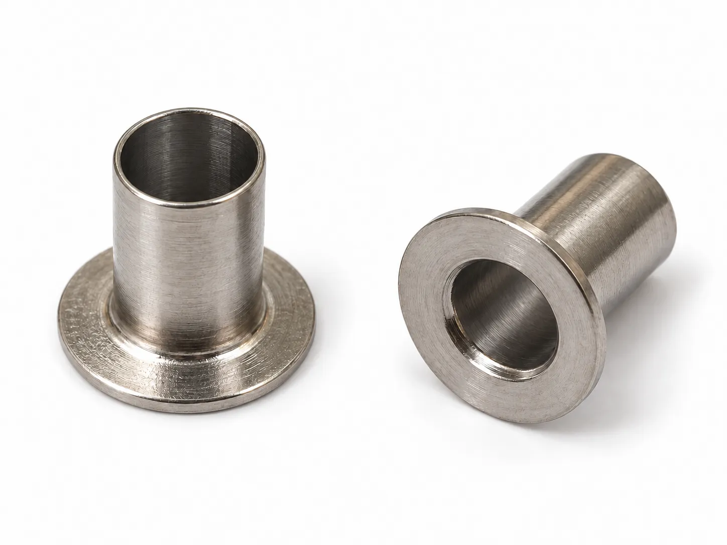
A flanged sleeve has a simple layout: the barrel enters a mating hole, an annular flange stays outside, and the bore provides a passage. Its job depends on which surface locates it, where loads travel and whether the free end is later clinched or joined.
Open-ended drawn parts with flanged ends also belong to the industrial eyelet family.[1] A useful initial description is a stainless steel deep-drawn flanged sleeve. Define it more specifically as an eyelet fastener when rolling or flaring the free end is part of the assembly plan.
The flange provides a shoulder; the barrel and bore define the fit
The flange can limit insertion, form the head of a clinched joint or provide an assembly contact face. The barrel outside diameter relates to the mounting hole; the bore relates to the screw, rod or other part passing through it. Stimpson likewise identifies flange diameter, barrel diameter, length under the flange and inside diameter as separate eyelet dimensions.[2]
Mark the actual contact surfaces on the assembly drawing. If the barrel presses into a housing, its outside diameter and the housing hole control that fit. If a rod moves inside, the bore and its axis matter; an acceptable outside diameter does not establish an acceptable guide fit. Allow room for the formed flange-root radius, which could otherwise prevent the flange face from seating.
Screen five potential uses by their assembly function
Start with function before selecting an industry label. Related drawn eyelets are used in appliance and consumer products, and eyelets and rivets are established categories in electronic assembly.[1][3] These examples support application research; they do not qualify an unidentified sample for a specific duty.
| Application direction | Possible function | What must be established |
|---|---|---|
| Locating bushing or distance sleeve in appliance and equipment parts | The barrel enters a hole; the flange provides an axial stop, or works with other parts to maintain spacing. | Hole-to-barrel fit, actual support surfaces, length, retention and loads. |
| Tubular eyelet in electronics or light hardware assembly | The flange seats on one side and the free end is clinched to grip the material stack. | Stack thickness, clinch allowance, delivered material condition and the installed joint's grip and cracking checks.[3] |
| Compression limiter in a plastic screw joint | A screw passes through the bore while the sleeve participates in carrying axial clamp load. | Sleeve length relative to plastic thickness, screw preload, end support and compression performance.[4] |
| Guide or mounting sleeve in valves, temperature controls or instruments | The barrel locates or guides an internal component; the flange provides axial location. | Bore fit, roundness, straightness, surface and material requirements; joining and sealing for fluid duty.[5] |
| Passage fitting in a housing | A designed joint retains the flange at the wall while the bore provides a vent or drain passage. | A geometry-based design possibility requiring a defined joint, seal, medium, temperature and pressure validation. |
Locating and eyelet fastening can first be assessed from the assembly layout. Compression limiting, moving guidance and fluid service also require their own mechanical, friction or sealing conditions. Until these are known, sleeve is a more accurate description than bearing or pressure fitting.
Retention changes the length, edge and support requirements
A flange stops movement in one direction; it does not automatically retain the sleeve against withdrawal. Specify whether retention comes from a press fit, clinching, screw clamping or a joining operation. These approaches are not interchangeable on appearance alone.
- Press or slip assembly: define the mounting hole, barrel diameter and engaged length together. Installing a thin wall can change the bore shape, so a guide application may require checks after installation.
- Clinch assembly: leave barrel length for the setting tool. Trial the actual material stack and tooling, then check for cracking and adequate grip. Keystone also calls for clinch allowance and trial riveting.[3]
- Screw clamping: check that both sleeve ends are in the intended load path. A compression limiter's length, plastic thickness, bearing faces and clamp load must be considered together.[4]
- Welding or another joining process: identify the joint and acceptance surfaces. Check distortion, cleanliness and, where needed, leakage after joining; a flat flange is only one element of a sealed assembly.
Define six groups of functional drawing requirements
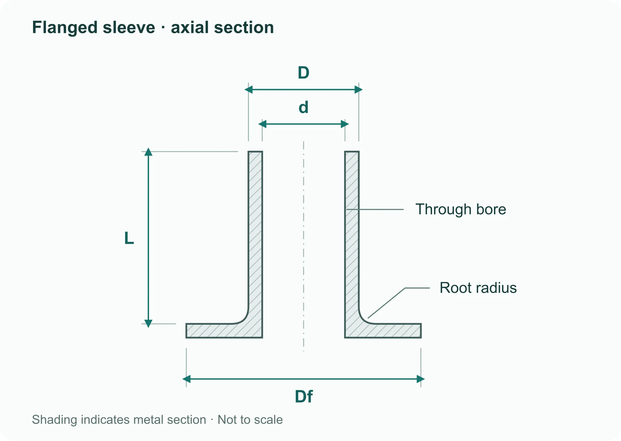
Inside diameter, outside diameter and wall thickness are geometrically related. Identify the mating surface before setting tolerances and measurement positions. Define the flange separately: diameter affects coverage, while thickness, the face and the root radius can affect support and clearance.
| Drawing item | Why it matters | What to specify |
|---|---|---|
| Barrel outside diameter D and bore d | They relate to the external mounting hole and the internal mating part. | Mating components, engaged length, tolerances and measurement sections; installed requirements where needed. |
| Projection L | It affects insertion, spacing or barrel length available for clinching. | Start and end faces, end condition, and whether the dimension applies before or after assembly. |
| Flange diameter Df and thickness | They affect coverage, support and available space. | Permitted contact area, flange face and geometric relationship to the barrel axis. |
| Wall and root radius | They affect diameter relationships, local strength and mating clearance. | Finished wall, permitted minimum, measurement positions and functional radius limits. |
| Both openings and edges | Burrs or handling damage can affect insertion, clinching and joining. | Edges touching a mating part or wire, required edge treatment and any later clinching operation. |
| Material condition and surface | They affect forming, subsequent setting, service environment and appearance. | Stainless grade, delivered condition, cleanliness and finish; mark unresolved items for review. |
Review forming together with the next assembly operation
Review the thin barrel, flange and through bore as one finished part. A photograph cannot establish draw count, opening sequence or intermediate treatment. Outokumpu distinguishes deep drawing, stretch forming and ironing within press forming, and identifies tooling surfaces and lubrication as important to the formed surface.[6]
If the free end will be clinched, the delivered part must also tolerate that later operation. Successfully drawing a sleeve does not prove it can be flared with any tool or allowance. Trial the actual part, setting tool and stack. Softening after cold working depends on the stainless grade and purpose; one annealing schedule cannot be assigned to every sleeve.[7]
Quote and approve the delivered condition: whether the bore is fully open, whether both ends are trimmed and deburred, which faces may retain forming marks, and who completes any later joining or cleaning.
Check dimensions alongside the installed result
For an ideal concentric tube at one section, wall thickness is t = (D − d) / 2. In a hypothetical example, D = 8.0 mm and d = 7.2 mm give t = 0.4 mm. This is a nominal geometry calculation; it does not prove that every point along or around a drawn sleeve has a minimum wall of 0.4 mm.
Begin sample inspection with three tasks: measure fit dimensions and wall at agreed sections; examine the free end, root and flange for cracks, burrs and handling damage; and use the mating parts to check seating, insertion and retention. Avoid visibly distorting a thin wall with measuring or holding force. Agree a gauge or installed-state check where appropriate.
Match performance checks to the function: clinched shape and retention for an eyelet; compression under specified conditions for a limiter; fit and operation for a moving guide; and agreed leakage conditions for a fluid assembly. Appearance or dimensional acceptance cannot substitute for an assembly performance test that has not been carried out.
Start with the assembly, even if the part name is uncertain
On an existing drawing, mark the mating faces, retention method and critical dimensions, and include expected quantities. If only a sample or photograph is available, explain where the sleeve fits, what passes through it, whether its free end is clinched and what assembly problem needs resolving.
Material, tolerances or finishing can be marked as undecided. Reviewing those questions explicitly gives a more useful basis for a process plan and quotation than assigning a bearing, rivet or fitting specification from appearance alone.
- [1] National Die Company — Deep Drawn Eyelets
- [2] Stimpson — Eyelet terminology and measurement
- [3] Keystone Electronics — Eyelets & Rivets, Catalog M55 p. 124
- [4] SPIROL — Metal Compression Limiters
- [5] PressTeck — General Brochure, Industrial Parts, printed p. 9
- [6] Outokumpu — Forming of stainless steel, Press forming and Hole flanging
- [7] Outokumpu — Post-fabrication treatment, Heat treatment and Solution annealing