When comparing stamping quotes, first confirm that each route delivers the same finished shape to the same acceptance requirements. Then compare tooling and unit costs. The table below gives an overview of operations and handling, followed by washer and cup examples to explain the choices.
What is the actual difference between progressive stamping and deep drawing?
Progressive stamping describes production organization: a strip advances by a fixed distance through a sequence of stations. Deep drawing describes deformation: a punch draws sheet into a cavity while surrounding material flows inward. A progressive die can therefore include drawing stations as well as piercing, trimming and bending stations. [1][2]
Single-station describes the working location. Compound cutting combines operations such as piercing and blanking at that location in one stroke, so a compound cutting die can also be a single-station die. [1]
This distinction changes how quotes should be compared. For a seamless cup, compare separate drawing dies, progressive drawing and transfer drawing where feasible. A quote for a flat pierced blank does not become an equivalent alternative simply because its tooling is cheaper.
| Tooling arrangement | How the part moves | A useful starting case | What to check |
|---|---|---|---|
| Separate single-station dies | A blank or part is loaded for each operation | Simple parts, uncertain demand or separate drawing stages | Handling, repeated positioning and the full set of required dies |
| Compound cutting die | The part stays at one station for combined cutting | Flat washer or plate with related inner and outer profiles | Cutting clearance, part ejection and any later forming |
| Progressive die | The developing part travels with a strip carrier | Stable brackets, contacts or suitable drawn cups | Carrier strength, material use, forming clearance and design stability |
| Transfer tooling | Separate blanks or parts move between stations | Drawn shells or parts needing free movement between stages | Gripping access, positioning, transfer motion and total tooling scope |
When do single-station and compound dies make sense?
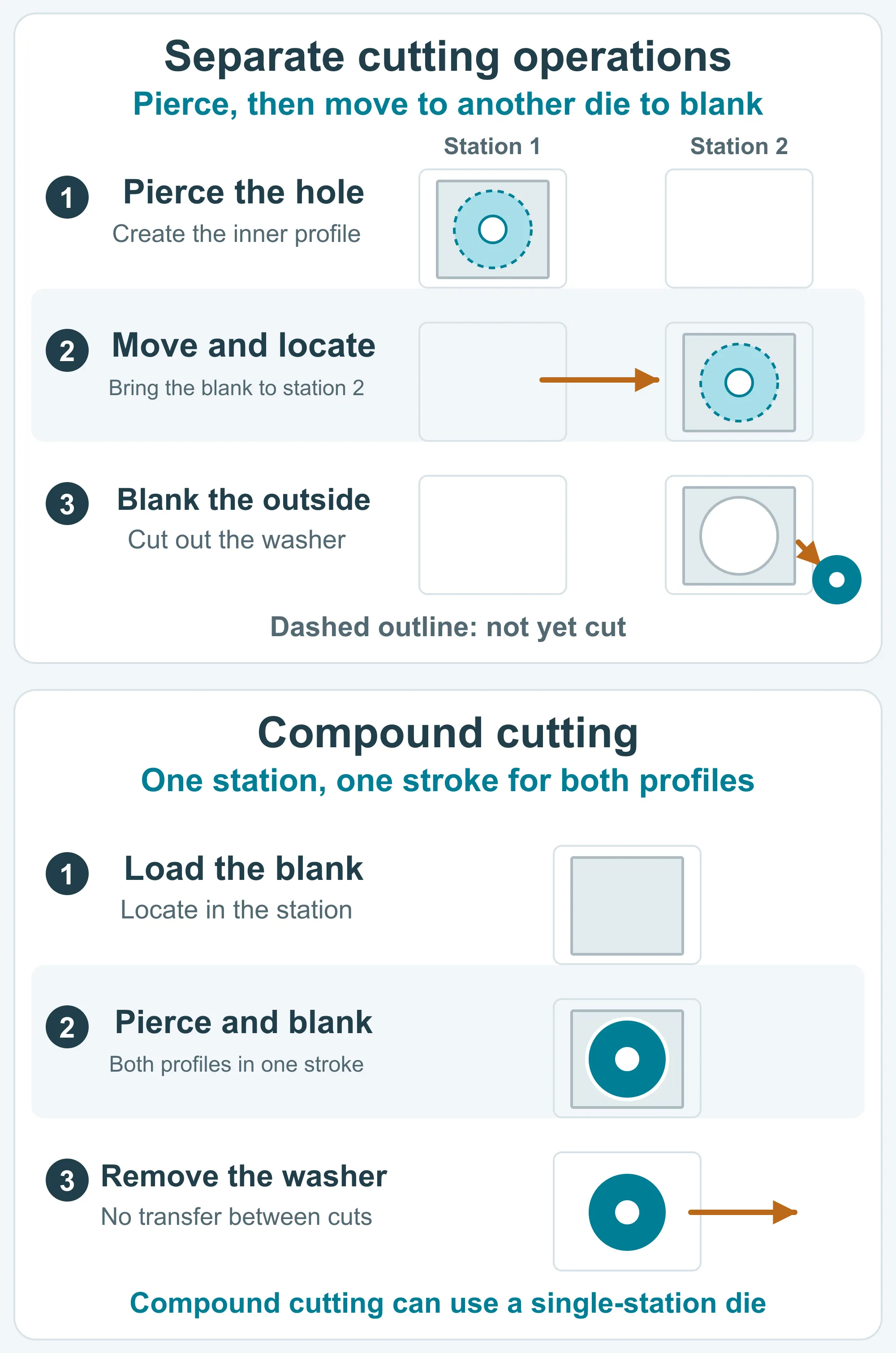
Single-station dies are worth considering when the operation is simple, demand is uncertain or individual forming steps need separate access. A compound cutting die can be useful for flat parts whose inner and outer profiles must be produced together. Neither label guarantees the lowest finished-part cost or a particular tolerance.
Consider a flat washer with one hole. Piercing and blanking in a compound die can establish the two profiles in one stroke, avoiding transfer between those cutting operations. If the part also needs a bent tab, the quote must include the bending operation and its setup or an alternative combined route.
Separate dies can make a local design change easier to isolate. The tradeoff is repeated loading, positioning, handling and possibly work-in-progress between steps. For a drawn shell, even a low-volume route may need several dedicated forming dies; low quantity does not remove the geometry requirements. [1]
What makes a part suitable for progressive or transfer tooling?
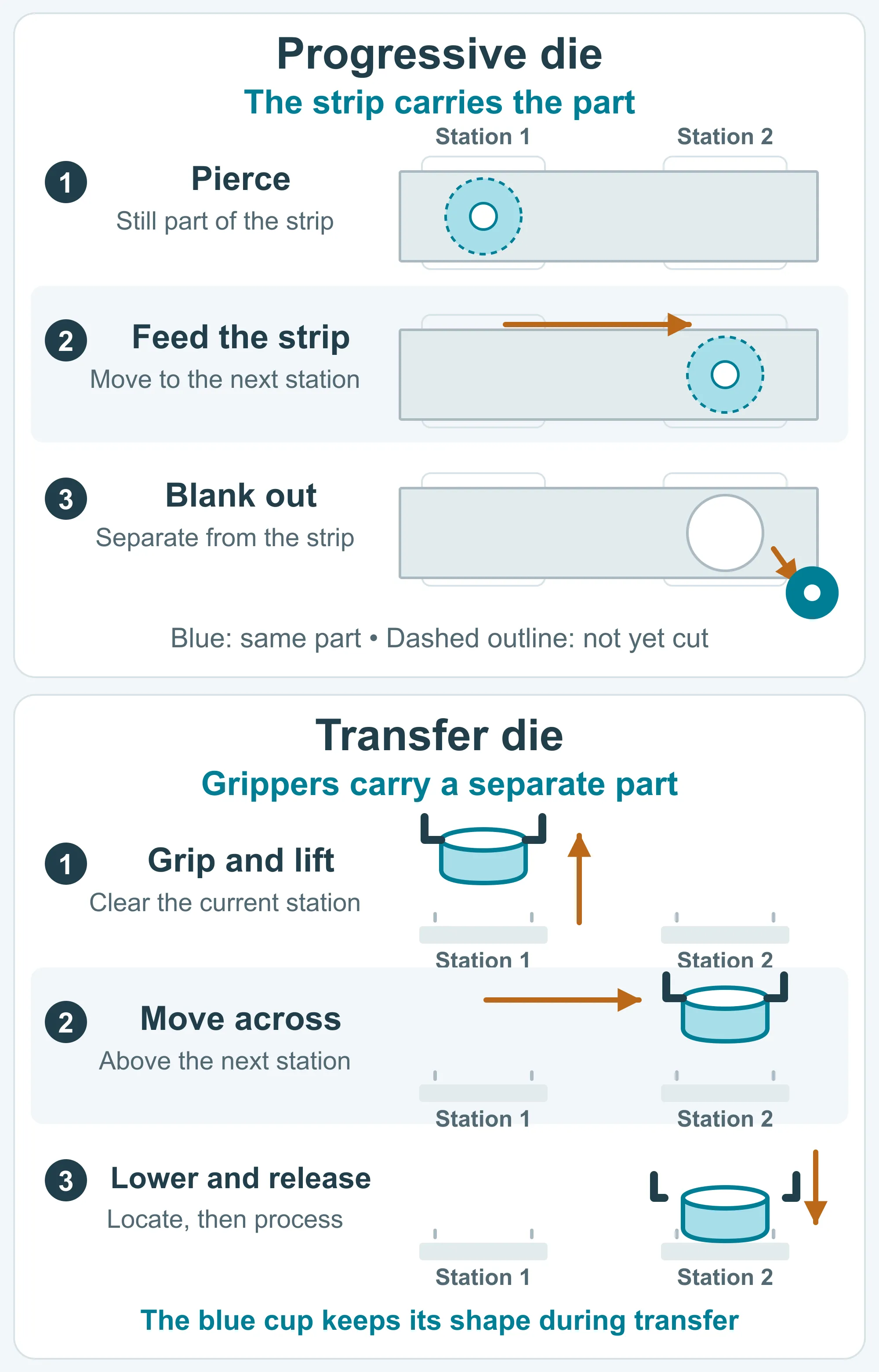
Progressive tooling is attractive when a stable part can remain connected to a strip throughout an economical sequence of operations. Transfer tooling becomes useful when a separate blank needs freedom to draw in, be repositioned or move between forming stages. Size matters, but strip support, access and material flow often decide the route. [1][2]
In a progressive die, the carrier is the remaining strip material that holds the developing part. It must survive feeding and forming, provide space for the next operation and release the finished piece at the planned cutoff. A deeper form also needs enough lift and clearance to advance without striking the tooling.
Transfer tooling removes the need to carry every part on the strip, but introduces gripping, positioning and synchronized motion. Engineers need accessible pickup areas and room to lift the part out of each station. A fragile rim or cosmetic wall may constrain where a gripper can touch.
The progressive example omits other parts on the strip; the output arrow indicates separation, not a specified ejection direction. The transfer example shows handling only: the cup keeps its shape in transit, and the next forming operation follows placement, location and gripper clearance.
- Pierced bracket with repeated bends: review progressive tooling when demand and the drawing are stable; confirm the carrier does not obstruct the bends.
- Small drawn cup with a flange: progressive drawing may work if strip connections allow the required inward flow and station clearance.
- Shell needing several draws or reorientation: compare a transfer route with separate drawing operations; do not assume that all hollow parts require transfer.
What should be checked before selecting a deep-drawing route?
Deep-drawing feasibility depends on how much material must flow into the wall and whether it can do so without unacceptable wrinkling, thinning or splitting. Material grade and condition, blank shape, corner radii, friction and restraint all affect that balance. The final depth by itself cannot specify a draw sequence. [2][3]
The blank holder helps control flange flow. Insufficient restraint can allow wrinkles; excessive restraint can restrict flow and contribute to thinning or splitting. Drawing also involves some stretching, so a seamless shape does not imply that the wall retains perfectly uniform starting thickness.
A redraw reshapes an already drawn part in another forming stage, often reducing its diameter and increasing its depth. Additional draws, trimming, sizing or intermediate heat treatment depend on the geometry and material. They should be identified in the proposed route rather than hidden inside an unexplained unit price.
A simple cup example: why depth is only part of the answer
Consider an unflanged round cup with a diameter d = 20 mm measured at mid-wall thickness and a straight wall height h = 10 mm. Assume approximately unchanged thickness and omit corner radii and trimming allowance.
The blank must supply material for both the base and the wall. Equal surface areas give an approximate round-blank diameter D ≈ √(d² + 4dh) = √(20² + 4 × 20 × 10) ≈ 34.6 mm.
That estimate explains where the wall material comes from: a blank wider than the finished cup. It does not establish that one draw is feasible or provide a production blank size. Corner shape, actual thickness distribution, trimming allowance and material behavior still need review; a rectangular cup adds different flow demands at its corners.
How should tooling investment, volume and lead time be compared?
Compare total cost for acceptable delivered parts over the quantity you realistically expect to order. Include tooling, material use, production operations, inspection, finishing and maintenance. Progressive tooling can reduce repeated handling, but its financial value depends on the savings actually achieved, order continuity and how long the drawing stays unchanged.
Ask each quotation to identify the operation sequence, any separate forming or trimming steps and which costs are one-time, per batch or per part. Compare the same material, finish, acceptance requirements and delivery quantities. A fast press cycle cannot compensate for an expensive secondary operation that was left outside the quoted scope.
There is no universal annual-volume threshold for progressive tooling. A simple part with a compact die and a complex drawn shell with several stages have different economics. Use both an expected-demand case and a lower-demand case; include possible tooling changes if the design is still evolving. [1]
For timing, separate first sample, sample approval and production delivery. More stations can mean more tooling work and tryout, while a simpler route may require more handling in production. Ask which drawing decisions, material procurement and sample checks control the schedule instead of relying on the process name.
What should you confirm before approving the proposed route?
Approve a route against the part's function and the evidence from representative samples. The buyer should identify what must fit, seal, contact or remain visible; the supplier should explain how the process and inspection plan address those needs. You do not need to calculate drawing forces or design a strip layout to begin.
For a bracket, highlight the mounting holes and the surfaces that locate it in the assembly. For a cup or shell, identify the opening that receives a mating part, any sealing rim and surfaces where marks would be unacceptable. Those details help engineers decide where trimming, sizing or extra inspection is needed.
- Confirm the drawing revision, material and finish represented by the samples.
- Check agreed fit dimensions after all operations that can change them, including finishing when relevant.
- For drawn parts, review critical wall or corner thinning, cracks, wrinkles and rim condition using agreed acceptance criteria.
- If samples use a different route from production, record what they validate and which features still need confirmation with production tooling.