A drawing note such as “deburr all edges” can leave two suppliers quoting different work. One may remove the raised material on a flat face; another may round the perimeter and change its appearance. Both need a clearer description of what the assembled part must do.
For an enclosure or bracket, start at the interfaces. Where will someone handle the panel? Where can a cable move? Which flange must sit flat? Which holes must retain the edge specified for the chosen fastener? This guide turns those questions into a practical edge-treatment and sample-acceptance plan.
Burr removal, edge rounding and surface finishing answer different questions
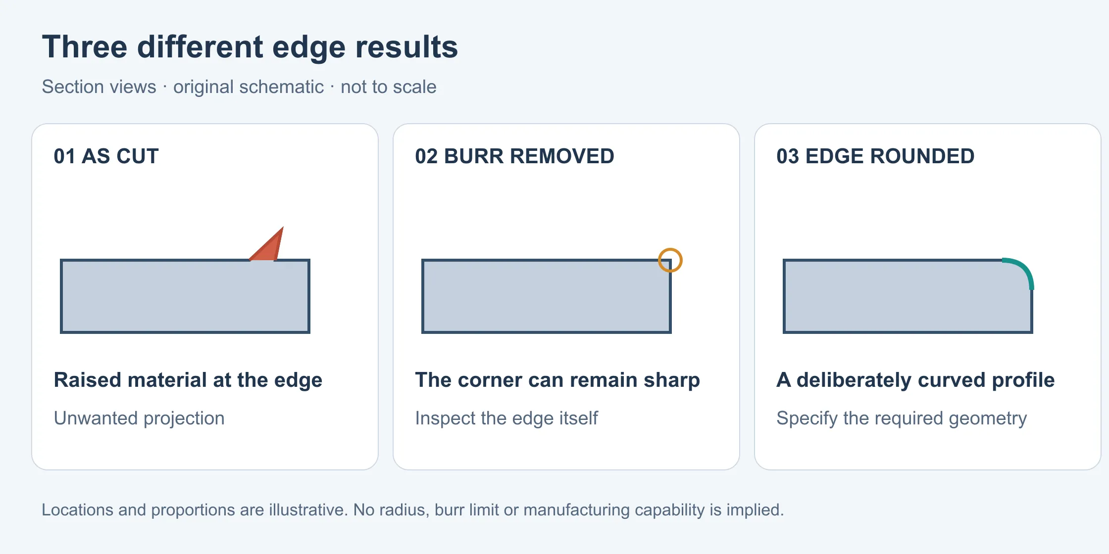
A burr projects beyond the intended cut edge. Removing that projection can leave a relatively sharp intersection between the sheet face and the cut face. Edge rounding deliberately changes that intersection to a curved profile. Surface finishing changes the broader face texture or appearance. An abrasive operation can perform more than one of these jobs, but the drawing still needs to say which results matter. [1][2][6]
A smooth-looking panel therefore does not establish that a cable opening is suitable, and a burr-free edge does not establish a specified radius. Inspect the local edge and the adjacent face separately.
| Requested result | What to define | What it does not establish |
|---|---|---|
| Burr removal | Location, treated side and acceptable residual projection | A controlled radius or decorative face finish |
| Defined edge rounding | Required profile or radius range and affected edges | Acceptability of protected holes or hidden edges |
| Face finishing | Visible face, grain direction or agreed appearance sample | A safe cable route or the required hole geometry |
Group the edges by their job in the assembly
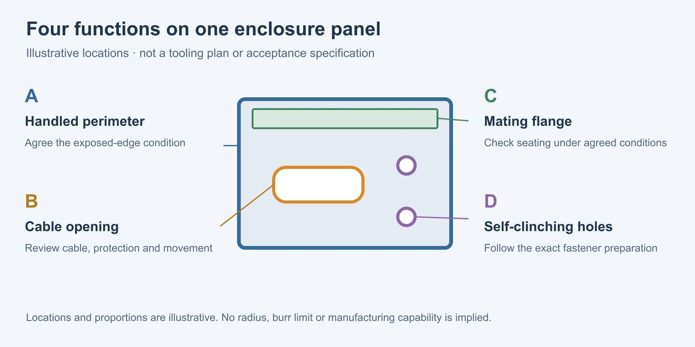
Use a marked drawing or photograph to distinguish the functional areas. This keeps a general edge note from overriding a specific hole, contact or sealing requirement. A useful mark identifies the location and the intended outcome; it does not require the buyer to select the abrasive grade.
| Area | Question to resolve | Sample check to agree |
|---|---|---|
| Handled perimeter | Which edges are exposed during assembly and normal use? | Defined edge condition on both relevant sides; inspect local starts, stops and corners |
| Cable slot or opening | Does insulation touch the edge or move across it? Is a grommet or liner required? | Edge geometry plus the intended cable, routing, protection and movement |
| Mating or sealing flange | What must contact the mating part, seal or gasket? | Residual protrusions, local geometry and seating under defined assembly conditions |
| Self-clinching mounting hole | What does the exact fastener catalog require? | Hole size and edge condition before installation; agreed installed-fastener checks |
| Visible or coated edge | Which texture, coverage and appearance are required? | Agreed appearance sample and coating acceptance after finishing |
Choose a process that can reach and support the feature
A local hand tool can target a particular accessible edge. Belt, disc or brush processing can treat accessible surfaces of a flat part, and abrasive tools may combine burr removal with edge rounding or finishing. The choice needs to follow the actual geometry and required result. [1][2][6]
Check the whole route around the part: the underside of a hole, a narrow slot, a recessed flange and the inside of a formed box may not be reached in the same setup. Ask which sides are processed, whether the part must be turned, and what happens after bending or another cutting operation. A process name alone does not answer those questions.
Compare representative samples when a part has thin tabs, small ligaments or a cosmetic face. Evaluate whether the proposed support and material removal preserve those features. A part-wide treatment should not be assumed equivalent to a controlled local edge treatment.
- Identify every required edge, including internal openings and the relevant face on each side.
- Agree which dimensions and appearance areas must be preserved.
- Check the final part after the complete manufacturing sequence; do not accept an early flat blank as proof of the formed assembly.
Protect self-clinching holes before applying a general deburring note
For the self-clinching fasteners covered by its handbook, PennEngineering warns against deburring mounting holes before installation: removing the surrounding metal can remove material needed to form the interlock. Hole size and preparation are part of the fastening system. [3]
Flag these holes separately and use the requirements for the exact fastener type, sheet material and thickness. Resolve a conflict between a general edge note and the fastener drawing before production. Do not turn the handbook instruction into a rule to leave every hole untouched, or into permission to retain uncontrolled loose burrs elsewhere.
If a finished hole has already been chamfered, rounded or enlarged, check it against the approved preparation requirements before installing the hardware. Confirm the relevant retention and assembly requirements on representative samples.
Separate coating preparation from the edge-shape requirement
Cut-edge oxide and a raised burr are different conditions. Where steel cut edges have an oxide layer that must be removed for the chosen coating process, specify that preparation separately. LISSMAC describes oxide removal on laser- and oxy-cut steel as a preparation step for coating. [4]
An edge-treatment plan also needs to state which faces may be abraded and which finish must remain. If abrasion removes an existing coating and exposes base metal, the required final coverage needs to be resolved in the finishing sequence. Neither a rounded edge nor a clean-looking face proves that the completed coating meets its acceptance criteria.
Review the edge before coating when that geometry will later be obscured, and inspect the delivered coating and assembly afterward. Coating must not be used as the assumed remedy for a protrusion or a geometry problem.
Write an inspection plan that can be repeated
Define what is being checked, where it is measured and whether acceptance applies before coating, after coating or in the assembled condition. If the drawing requires a particular radius or chamfer, name and dimension that geometry. ISO 13715 addresses the indication of edges of undefined shape; its public scope distinguishes them from explicitly defined edge geometry. [5]
A visual check can locate a remaining projection or missed area. A dimensional requirement needs an agreed measurement method with suitable resolution, access and reference surfaces. Select an appropriate profile or optical method for a small edge feature where needed; a face-roughness reading does not directly measure burr height or edge radius.
Use the same feature list and measurement conditions for sample approval and repeat deliveries. For a functional check, document the actual mating item and conditions. A photograph, handling impression or successful first fit can support a review, but it should not replace a dimensional requirement that the drawing actually specifies.
- Locations: perimeter segments, hole exits, slot corners and operation transitions.
- Limits: drawing-defined residual material, allowed material removal and any required edge profile.
- Condition: uncoated, coated, free-state or assembled, as appropriate.
- Method: lighting or magnification, dimensional instrument, inspection positions and sampling agreement.
- Record: drawing revision, accepted sample identity and any explicitly approved exceptions.
Example: mark an enclosure panel before requesting a quote
Consider an illustrative enclosure panel with a handled perimeter, a cable slot, a cover-mating flange and self-clinching nut holes. Mark them A, B, C and D instead of relying on a single undifferentiated edge note.
A identifies the handled perimeter and the edge condition to agree. B identifies the actual cable path and any liner or grommet. C identifies the seating area and the agreed flange condition. D refers to the selected fastener’s mounting-hole preparation. The markings describe four different acceptance questions on one part, not four prescribed machines.
Send the marked drawing, sketch or photo with the material and thickness if known, expected quantities and the intended finish. Explain which edges touch people, cables or mating parts. Where the edge requirement is still undecided, mark it for discussion so the drawing review and quote can address it.