A straight, attractive weld does not prove that a thin-sheet assembly is dimensionally stable, corrosion resistant or as strong as the parent material. Welding changes temperature, stress, surface condition and, for some alloys, microstructure. Joint geometry can create a separate corrosion problem even when the weld itself looks acceptable.
For a thin-sheet enclosure, work through three linked questions: where will weld shrinkage move the assembly, what will heat change in the chosen alloy, and where could the finished joint retain moisture or residue? The sections below turn those questions into a drawing review, a control sequence and an inspection example.
What must a welded enclosure drawing define?
A quote-ready welded enclosure drawing defines material grade and condition, thickness, joint type, weld location and extent, assembly datums, critical dimensions, cosmetic faces, prohibited heat-affected zones, cleanup or finish requirements and the inspection state. It also names which strength, sealing, corrosion or system tests remain buyer-owned instead of leaving acceptance to bead appearance.
Send the controlled 2D drawing and STEP/STP assembly together. Show mating parts and the order-sensitive features around bends, inserts, covers and gaskets. If the supplier may propose a different joint, weld length or assembly sequence, mark that item as open for DFM rather than allowing an unrecorded shop-floor substitution.
- Material grade, temper or condition, thickness and allowed substitutions.
- Joint geometry, weld side, length or spacing, start and stop zones and access limits.
- Functional datums, critical fit dimensions and whether inspection is free-state, restrained or assembled.
- Cosmetic surfaces, grinding or cleanup notes, spatter limits and finish sequence.
- Gasket, grounding, masked, threaded and corrosion-sensitive interfaces.
- Sample, first-article and production inspection records required by the buyer.
- Buyer-owned joint, leak, ingress, corrosion, fatigue or product-level validation when applicable.
Why does sheet metal distort after a weld cools?
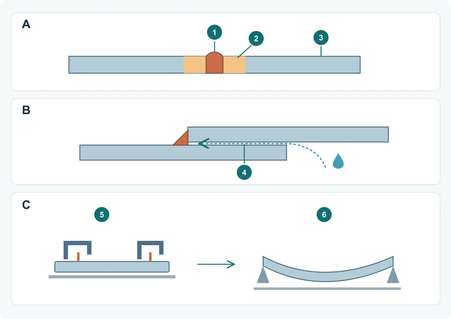
Localized weld heat makes the weld zone expand while colder surrounding sheet restrains it. If the resulting thermal stress causes local plastic strain, cooling cannot return the assembly to its original shape. Weld-metal and heat-affected-zone contraction then leave transverse or longitudinal shrinkage, angular change, bowing, dishing, buckling or twist; thin panels are especially buckle-prone.
Control begins before welding. Review whether the joint needs the specified weld volume, whether the fit-up is uniform, where shrinkage can move the assembly and which datum must stay stable. Balanced or intermittent layouts, tack strategy, sequence, fixturing and preset can be evaluated for the actual geometry. More restraint is not automatically better because it can raise residual stress or cracking risk.
Intermittent welds can reduce deposited weld volume when the approved design permits them. They are not a substitute for a required continuous sealed seam. Likewise, lower heat input is useful only while the process still achieves the required fusion and joint performance; changing current or travel speed alone is not a complete distortion-control plan.
- Name the critical flatness, angle, opening or interface instead of asking for a generally straight assembly.
- Use the minimum weld extent that satisfies the buyer's approved joint design.
- Keep fit-up and gaps controlled so heat and shrinkage are not concentrated unpredictably.
- Agree the tack, weld and inspection sequence before inaccessible panels or finishes are added.
- Validate the proposed fixture and measurement condition on representative samples.
Why can stainless steel corrode under bolts, washers and lap joints?
Stainless steel relies on an oxygen-supported passive surface film, but a narrow, wet crevice under a washer, around a bolt shank or inside a lap joint can become stagnant and oxygen depleted. Metal ions accumulate, chlorides can migrate inward and local acidity rises until the passive film breaks down, allowing localized crevice corrosion to become self-sustaining.
This mechanism is different from galvanic corrosion, which requires dissimilar materials and an electrical path. A stainless joint can suffer crevice corrosion by itself. The drawing should therefore define the environment, drainage and cleaning access, whether the crevice is deliberately open or sealed, mating materials, surface cleanup and the project-specific inspection or corrosion test. A more resistant grade is not immunity.
- Avoid pockets that trap water, cleaner, salt or process residue.
- Show whether lap seams, gasket edges and fastener interfaces must be open, drainable, cleanable or sealed.
- Do not treat an insulating washer as proof that crevice corrosion has been prevented.
- Separate crevice-corrosion review from galvanic-corrosion review when dissimilar metals are present.
- State cleaning, passivation or finishing requirements and the buyer's acceptance basis on the drawing.
Why can 6061-T6 aluminum soften beside a weld?
6061-T6 gets much of its strength from fine precipitates created by solution heat treatment and artificial aging. A welding thermal cycle can dissolve, coarsen or over-age those precipitates in the heat-affected zone. The weakest location may therefore sit beside the weld rather than in the weld bead, even when the joint looks sound.
Do not use the parent T6 datasheet value as the automatic welded-joint allowable. Joint properties depend on alloy, temper, thickness, process, heat input, filler, geometry and any post-weld treatment. The responsible engineer should define the welded-condition design basis and validation method; a visually sound bead does not establish the strength of the adjacent material.
Set the control sequence before adjusting welding parameters
Start with the joint and assembly constraints. A fixture can hold an opening in position while welding, but the assembly may move after release. Record how the joint was fitted, tacked, welded, cooled and released so a trial result can be repeated.
- 1. Fit-up: check gaps, mating edges and datums before tacking; do not use excess weld metal to hide an inconsistent fit.
- 2. Tacking: agree locations and order that maintain the joint gap; check that tacks do not obstruct the following weld or cleanup.
- 3. Welding: evaluate balanced, back-step or skip sequences where suitable, while preserving the specified weld size and final continuity.
- 4. Cooling and release: define the release condition and support points, then measure the named interfaces. Compare one planned change at a time on representative samples.
Use a released-part measurement to judge the trial
Teaching example: the drawing requires a clear opening of 200 ± 0.5 mm between two marked faces after cooling, with the assembly resting on specified supports and no lateral clamps. A trial reads 200.1 mm while clamped and 199.2 mm after release. The accepted interval is 199.5–200.5 mm, so the released assembly fails that requirement even though the clamped reading passes.
Record the two values as different measurement states. Review joint fit-up, tack and weld sequence, and fixture release before changing the drawing or forcing the cover into place. Check the revised trial in the same released state. If the product instead specifies inspection under an assembly load, record that load and method explicitly; the two results are not interchangeable.
Plan post-weld cleanup while the surfaces remain accessible
On stainless steel, removing visible discoloration is not the same as restoring the required surface condition. Outokumpu notes that brushing can remove superficial heat tint while leaving the chromium-depleted layer below it. Specify the required post-weld condition and a suitable cleaning route, including rinse and residue checks, before installing hardware or closing inaccessible joints.
For a lap seam, decide whether the joint will exclude moisture with a verified seal or remain drainable and cleanable. A partial seal can leave a trapped crevice. Show the exposed side, sealing boundary and cleaning access on the drawing, and connect the corrosion test to the expected environment. Passivation is not a general substitute for removing weld oxide or trapped contamination.
How should a welded sheet metal assembly be approved?
Approve the assembly against the controlled drawing in a defined physical state. Check material and condition, critical datums, gaps, angles, flatness, hardware and surface condition before judging the weld itself. Then apply the project-specific joint or system tests owned by the buyer. A sample that looks straight does not establish repeatability or product compliance.
The inspection plan should match risk. A cosmetic cover, structural bracket, sealed box and conductive chassis do not need the same evidence. Record fixture or restraint state, measurement tools, sample frequency, defect examples, repair rules and the drawing revision. If a weld, cleanup route or material condition changes, reassess the affected approval evidence instead of treating it as an invisible process substitution.
- Confirm material identity, thickness and temper or condition where relevant.
- Measure named datums, flatness, angles, openings and mating interfaces in the stated condition.
- Inspect weld location, extent, starts and stops, cleanup, spatter and cosmetic zones.
- Inspect stainless crevices, drainage, deposits and post-weld surface requirements where exposure makes them relevant.
- Use buyer-defined joint or functional tests for strength, sealing, ingress, fatigue, corrosion, grounding or system performance.
- Link the approved sample, inspection record and any repair acceptance to one drawing revision.
What belongs in the final welding RFQ checklist?
A useful welding RFQ lets the supplier see the complete load, fit, surface and inspection problem without asking the supplier to invent product requirements. Send the same controlled package to every bidder, identify which decisions are fixed and which are open for DFM, and require every proposed material, joint or sequence change to be recorded before approval.
- Revision-matched 2D drawing and STEP/STP assembly.
- Material grade, condition, thickness, surface and substitution rule.
- Joint type, weld side, extent, access and no-weld zones.
- Critical datums, tolerances and inspection restraint state.
- Mating parts, fasteners, inserts, gaskets and assembly sequence.
- Cosmetic faces, weld cleanup, passivation or other finish notes and masking.
- Environment, drainage, crevice and dissimilar-metal information.
- Prototype, first-article and production quantities.
- Required dimensional, visual, nondestructive or functional evidence.
- Buyer-owned validation and change-approval responsibilities.
- If some items are still undecided, mark them as open and send what you have. We can compare the options with you during DFM and agree on practical requirements; you do not need to finalize every detail before the first RFQ.
| Effect | Why it happens | What the RFQ should define | Do not assume |
|---|---|---|---|
| Weld distortion | Restrained local heating and uneven contraction leave permanent strain | Joint, weld extent, datums, sequence constraints, fixture and measurement state | A straight sample proves repeat production |
| Stainless crevice corrosion | Stagnant shielded electrolyte becomes oxygen depleted, acidic and chloride concentrated | Environment, joint drainage or sealing, cleanup, surface condition and test basis | Stainless or an insulating washer makes the joint immune |
| 6061-T6 HAZ softening | Weld heat changes the fine precipitates that provide T6 strength | Alloy, temper, joint design basis, process condition and buyer validation | Parent-material strength applies across the weld |
| Movement after fixture release | Restraint can hide deformation until the part is released | Support points, release condition and inspection state | A clamped dimension equals a free-state dimension |
| Stainless surface after welding | Heat tint or residue can leave a corrosion-sensitive surface | Cleanup access, oxide removal, rinsing and final surface acceptance | A bright-looking weld proves restored corrosion resistance |