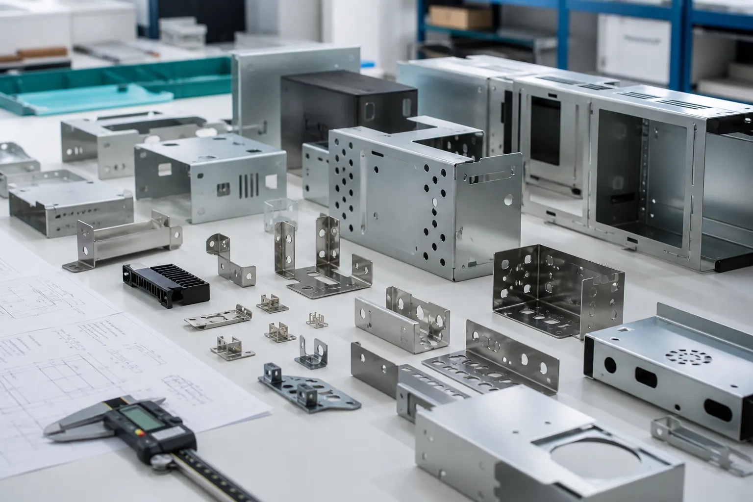
Sheet metal bending DFM makes a formed part compatible with the material, press brake, tooling and inspection method that will produce it. A model can fold perfectly on screen while the shop encounters an unsupported flange, a distorted hole or a flat pattern calculated from the wrong bend data.
This guide covers cut blanks bent sequentially on a press brake for enclosures, chassis, panels, covers and brackets. It is not a progressive-die stamping standard. The values below are design-screening guidance, not fixed HARVLAND tolerances or guaranteed machine limits. Confirm critical features against the selected material, thickness, bend method and supplier tooling before production release.
Start with the correct process: press-brake bending, not stamping
In fabrication, a laser or punch cuts the blank and a press brake forms one bend at a time. The setup must support the part, avoid collisions and place each bend in a workable sequence. Flexible tooling makes this route suitable for prototypes, enclosures and low-to-medium volumes.
A stamped bend is developed inside a dedicated die, often with piercing or other forming stations. Strip layout, carriers, station sequence and die clearances introduce different constraints. Do not transfer a progressive-die bend allowance or tolerance directly to a press-brake flat. Name the expected route and volume in the RFQ, or ask the supplier to compare both routes.
Neutral axis and K-factor: what the flat pattern is modeling
During bending, the outside surface stretches and the inside surface compresses. Between them is a neutral axis whose length is treated as unchanged. It normally shifts toward the inside rather than staying at mid-thickness.
K-factor equals the neutral-axis distance from the inside surface divided by sheet thickness. CAD uses it, a bend table or bend deduction to develop the blank. It is not a permanent material constant: radius-to-thickness ratio, material condition, grain direction, bend method and tooling all influence it.
A generic CAD default can support an early concept, but critical flange locations need the fabricator's bend data and, when necessary, a coupon or first-article correlation. Record any approved value with its material, thickness, radius, angle and tooling context.
How to read a bend coefficient chart
A chart headed ‘bend coefficient’ does not tell you which flat-pattern method it uses. Read the formula and units first. If the instruction is ‘add the outside flange dimensions, then subtract this value once per bend’, that value is a bend deduction. Do not enter it in the CAD K-factor field.
A usable shop chart identifies material grade and condition, actual thickness, bend method, tooling including V-opening, achieved inside radius, finished angle and dimension endpoints. Check whether an entry applies to one bend or the whole part. Missing conditions make the chart a starting reference to investigate, rather than a released cutting rule.
| Quantity | Meaning and unit | How it is used |
|---|---|---|
| K-factor, K | Neutral-axis offset ÷ thickness; dimensionless | K locates the neutral axis in BA = θ × (π/180) × (R + K × T). |
| Bend allowance, BA | Developed arc length of the neutral axis; mm | Add BA to the straight lengths ending at the bend tangents. |
| Bend deduction, BD | Correction for outside flange dimensions; mm per bend | For the simple bend defined below: L = L1 + L2 − BD. |
| Normalized deduction, c = BD/T | Deduction divided by thickness; dimensionless | If the shop defines c this way, BD = c × T. This ratio is not K. |
Bend allowance, bend deduction and flat length
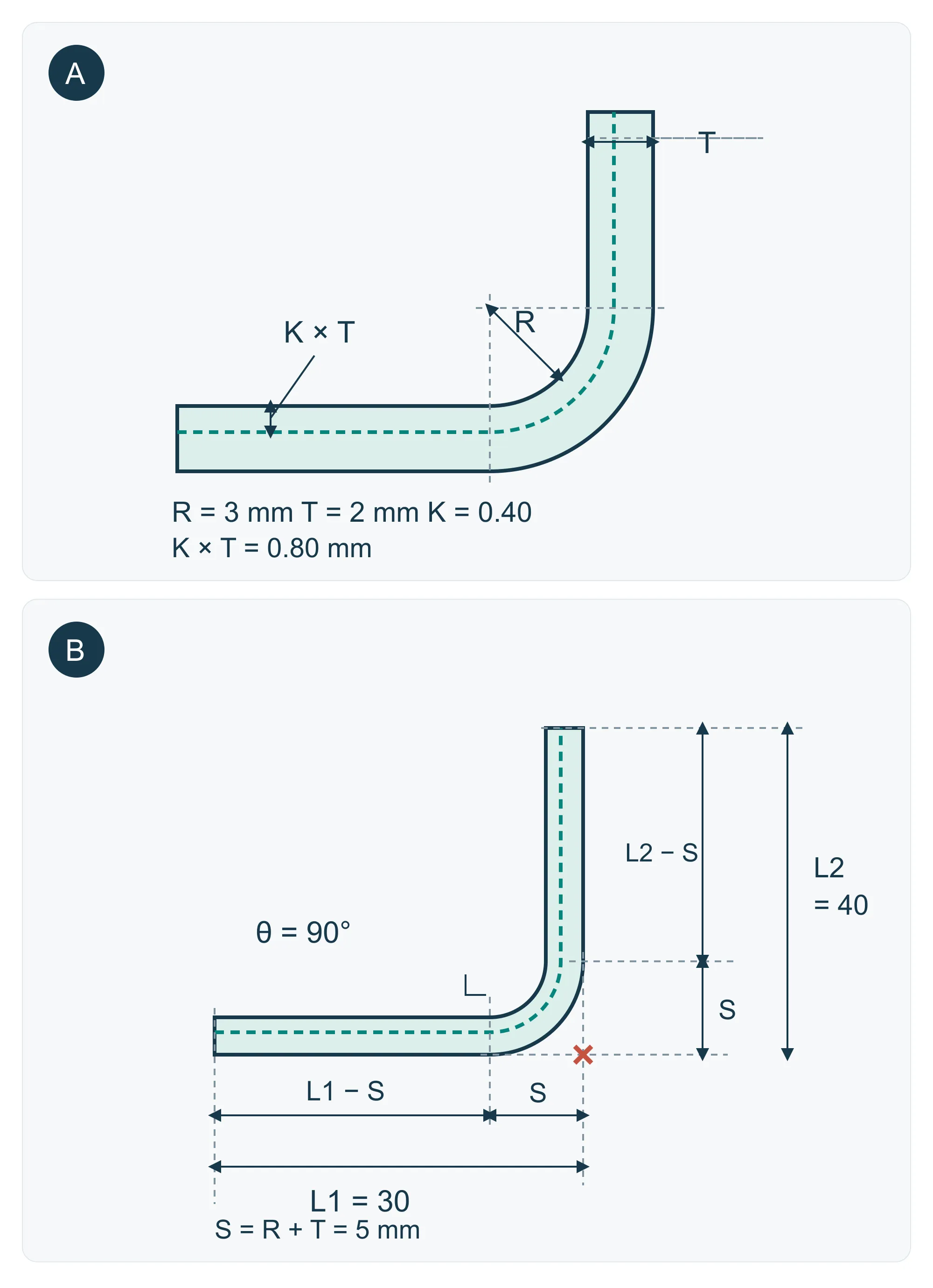
Bend allowance, BA, is the developed length along the neutral axis through the bend: BA = θ × (π/180) × (R + K × T). Here θ is the angle turned from flat, in degrees; R is the inside radius; T is thickness; and K × T is the distance from the inside surface to the neutral axis. Use the same length unit for R, T and BA. The SOLIDWORKS K-factor reference below uses this angle convention.
For a simple open bend, the included angle α between the flanges is 180° − θ. A 120° included angle therefore means θ = 60°, not 120°. At a right-angle bend both are 90°, so that example alone cannot expose an angle-convention mistake.
For outside flange dimensions L1 and L2 measured to their theoretical sharp intersection, the outside setback is S = (R + T) × tan(θ/2). Bend deduction is BD = 2S − BA, giving flat length L = L1 + L2 − BD. Alternatively, subtract S from each outside flange length and add BA to the two straight tangent lengths. These are two checks of the same geometry; do not apply another deduction after adding BA.
Calculation example: one 90° bend, R = 3 mm, T = 2 mm, assumed K = 0.40, L1 = 30 mm and L2 = 40 mm. Assume a uniform section and exclude coating and local thinning from this geometric model. The diagram defines the dimensions; its proportions are schematic.
- Neutral-axis offset: K × T = 0.40 × 2 = 0.80 mm; neutral-axis radius: R + K × T = 3.80 mm.
- Bend allowance: BA = (π/2) × 3.80 = 5.969 mm.
- Outside setback: S = (3 + 2) × tan(45°) = 5.00 mm; bend deduction: BD = 10 − 5.969 = 4.031 mm.
- Outside-dimension method: L = 30 + 40 − 4.031 = 65.969 mm, rounded to 65.97 mm.
- Tangent-length check: L = (30 − 5) + (40 − 5) + 5.969 = 65.969 mm. Use validated shop data before releasing the flat; K = 0.40 is an assumption for this example.
A bend coefficient table you can calculate back
The table below is a geometric calculation example, not a material lookup table. Every row assumes one 90° bend, inside radius R equal to thickness T, and K = 0.40. All lengths are in mm; the model assumes a uniform section and excludes coating and local thinning. R = T is a calculation condition, not a recommended minimum radius.
With these assumptions, BA = (π/2) × 1.40T ≈ 2.199115T and BD = 4T − BA ≈ 1.800885T. Thus a normalized deduction near 1.80 and a K-factor of 0.40 can describe the same assumed bend. Keep the unrounded calculation until the final result.
| T (mm) | R (mm) | K | BA (mm) | BD (mm) |
|---|---|---|---|---|
| 0.50 | 0.50 | 0.40 | 1.100 | 0.900 |
| 0.80 | 0.80 | 0.40 | 1.759 | 1.441 |
| 1.00 | 1.00 | 0.40 | 2.199 | 1.801 |
| 1.20 | 1.20 | 0.40 | 2.639 | 2.161 |
| 1.50 | 1.50 | 0.40 | 3.299 | 2.701 |
| 2.00 | 2.00 | 0.40 | 4.398 | 3.602 |
- For T = R = 1.50 mm and outside dimensions of 30 and 40 mm, L = 70 − 2.701327 = 67.298673 mm, or 67.30 mm. This differs from the earlier example, which uses T = 2 mm and R = 3 mm.
- For otherwise identical independent bends, subtract the matching deduction for each bend. Recalculate when radius, angle or process changes; do not carry this 90° table into a hem, a jog with interacting bend zones, or a different R/T ratio.
Build a shop bend table from trial bends
Use a simple single-bend coupon made with the intended material and tooling. Confirm the unloaded finished angle before adjusting the flat calculation: changing K changes the developed length in CAD, while springback compensation controls the formed angle.
For the simple geometry above, a known flat length L0 and measured outside dimensions give BD = L1 + L2 − L0. With the actual inside radius and bend angle, calculate BA = 2 × (R + T) × tan(θ/2) − BD, then K = [BA / (θ × π/180) − R] / T. All dimensions must use the same endpoints as the diagram.
- Record material grade/condition, measured T, grain direction, forming method, punch, die and V-opening. Measure the blank length L0 before bending.
- After unloading, measure the finished angle, inside radius and outside flange dimensions to their theoretical sharp intersection. Keep the measurement method consistent across coupons.
- Repeat the trial enough to assess variation, compare the predicted flat with the result, and record the accepted BD or effective K together with the tooling, date and revision. Do not treat one coupon as a universal material constant.
- Check a first article against the formed drawing and assembly dimensions. Revalidate when material condition, thickness, grain orientation, tooling or bend method changes.
Check the reverse calculation and the source of an error
Reusing the earlier teaching inputs, L0 = 65.97 mm, L1 = 30 mm, L2 = 40 mm, R = 3 mm, T = 2 mm and θ = 90° gives BD = 4.03 mm, BA = 5.97 mm and K ≈ 0.400. These are demonstration inputs, not measured trial results; the small difference from exactly 0.40 comes from rounding L0.
If the angle is correct but the overall developed length is wrong, check BD, the achieved radius and the dimension convention. If one flange is long while the other is short by a similar amount, check bend location and backgauge setup. Correct the identified cause before changing K.
Choose inside bend radius with material and tooling
Call out inside radius where it affects fit, strength or appearance. A radius near one thickness is a common early concept for some ductile mild steels, not a universal minimum. Harder grades, stainless steel and some aluminum conditions may need more radius, especially when bent parallel to grain. Burrs or scratches on the tensile side can also initiate cracks.
In air bending, achieved radius depends strongly on V-die opening, material and thickness; it may not equal the punch-tip radius. Bottoming and special forming behave differently. Unnecessary radius variety can add tool changes, so standardize non-critical bends where possible.
Ask the supplier to confirm achieved radius with the intended tool set. For a crack-sensitive or mating profile, define verification and approve samples made from the intended material condition.
Minimum flange length and press-brake access
A flange must remain supported by the die as the blank rotates. Its practical minimum depends on V-opening, tool profile, angle, radius and measurement convention. A rule such as four times thickness may flag risk, but it cannot confirm every shop's tooling.
A narrower die or special tool may form a shorter flange at the cost of force, marks, setup or radius risk. Return flanges, hems and deep boxes also need clearance from punch, die, ram and backgauge. An earlier wall can block a later bend.
Send the fully formed model and bend directions for sequence review. When a short flange is functional, identify why and allow a proposed tool radius or relief.
Hole-to-bend distance and feature distortion
Material near a bend stretches, compresses and slides. A nearby hole or slot may become oval, pull toward the bend or shift from its datum. Measure clearance from the feature edge to the bend tangent, not only from its center to a drawn bend line.
For early screening, an ordinary hole edge is often kept roughly R + 2T or more from the tangent; some shops or features use R + 2.5T or more. This is a review trigger, not an acceptance limit. Large slots, countersinks, lances, inserts and position-critical holes may need more space because material, V-opening and orientation change distortion.
If the feature cannot move, consider relief, post-bend cutting or a validated pre-bend shape. State whether diameter, position, edge distance or assembly clearance is critical so the supplier can assess the right risk.
Bend relief, corner relief and tear prevention
Where a bend ends inside a blank, material at the end may tear, bulge or pull the adjacent edge. Bend relief lets the flange rotate; corner relief manages the meeting point of multiple walls.
A concept check often starts near one thickness wide and extends about inside radius plus thickness beyond the tangent. This is not a fixed minimum: kerf, material, radius, finish and corner-gap needs control the final shape. Radiused relief ends can reduce stress concentration, while an oversized relief may expose or weaken the corner.
Show whether the corner stays open, is welded, receives a cover or carries a gasket. Include weld access and finishing rather than assuming welding removes all relief distortion.
Plan for springback, grain direction and bend sequence
Springback is elastic recovery after force is removed. Material strength, radius-to-thickness ratio and tooling influence it. The fabricator may compensate with over-bend, tool selection or trial correction. Specify the finished angle and tolerance; do not pre-distort nominal CAD unless that correction is agreed and controlled.
Bending across the rolling grain is generally less crack-prone than bending parallel to it, especially for harder stock. Mark grain direction only when functional because it can reduce nesting efficiency and raise material cost.
Sequence controls access and accumulated error. A tall wall formed early may block another tool, while several bends can stack variation. Identify assembly datums and critical formed dimensions, then let the supplier select a stable forming and inspection sequence.
Drawings, STEP models and flat-pattern control
Send a formed STEP/STP model and controlled 2D drawing. The model communicates finished shape; the drawing states material, thickness, bend directions, critical radii, datums, formed dimensions, tolerances, grain, finish and cosmetic faces. Dimension function after forming instead of over-defining conflicting flat and formed states.
A flat DXF/DWG helps nesting and estimating only when its revision and bend basis are clear. Label it reference-only or buyer-controlled and state its K-factor, bend table or deduction. The fabricator may regenerate it using validated shop data.
Avoid one tight tolerance across cut edges, angles and formed locations. Tighten connector positions, mating flanges, cover gaps or mounting datums where needed, and agree on normal process tolerances elsewhere. Inspection should use stable datums and the product's assembly condition.
RFQ and DFM checklist before first articles
Give engineering enough context to select tooling and flag risky features before price and lead time are fixed. Quantity can change the preferred route, and visible faces may need special handling for press-brake contact marks.
Request written DFM feedback instead of silent changes to radius, flat or hole location. Update both model and drawing, then verify assembly-critical formed dimensions on the first article.
- Provide formed STEP/STP, controlled PDF and a labelled flat DXF/DWG when available.
- State material grade, thickness, condition, finish, grain constraint and acceptable alternatives.
- Mark bend direction, finished angle, critical radius, datums and critical formed dimensions.
- Identify short flanges, close features, reliefs, hems, inserts and collision-prone walls.
- Define visible faces, tooling-mark limits, deburring, masking and prefinished material constraints.
- List prototype and annual quantities plus first-article measurements and assembly checks.
- Ask the supplier to confirm method, tooling, bend data, sequence and proposed changes.
| Design item | Practical starting point | What to confirm in DFM |
|---|---|---|
| Neutral axis | Model it inside the thickness, shifted toward the bend interior | Actual location for the material, radius and bend method |
| K-factor | Use a documented CAD estimate only for concept development | Validated bend table or coupon result for the selected process |
| Bend allowance or deduction | Use one consistent flat-pattern method | Angle convention, dimension convention and value per bend |
| Inside radius | Start near thickness only for a suitable, ductile concept | Achieved radius with the selected V-die, material and tooling |
| Minimum flange | Check against V-opening and tool support, not one universal T multiple | Tool access, backgauge support, force and bend sequence |
| Hole-to-bend distance | Screen ordinary holes around R + 2T or more from edge to tangent | Distortion risk for the actual feature, orientation and tooling |
| Bend relief | Start near T wide and extend about R + T beyond the tangent | Kerf, corner gap, crack risk, finish and welding requirement |
| Springback | Dimension the required finished angle | Shop compensation, sample result and realistic angle tolerance |
| Grain direction | Prefer bending across grain when crack risk matters | Stock orientation, nesting cost and whether a drawing note is required |