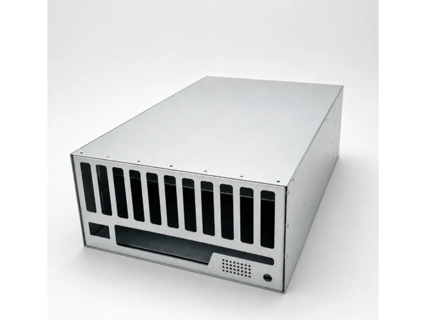
A sheet metal enclosure is rarely just cut and bent sheet. Most housings also need threaded attachment points, board standoffs, removable covers, rack ears, brackets or service panels. Those details may use self-clinching nuts and studs, rivet nuts, weld nuts, weld studs, solid rivets or captive screws, and the choice affects the flat pattern, bend sequence, finish route and final inspection.
Hardware should therefore be selected before the enclosure RFQ is treated as production-ready. This guide helps OEM buyers and mechanical engineers describe the fastening method without assuming that every insert fits every material or that an installed fastener automatically meets a torque, pushout or pull-through target.
Short answer: what to include in the hardware RFQ
For every installed fastener, identify the hardware family, manufacturer part number or approved equivalent, thread, installation side, quantity per enclosure and the drawing feature that locates it. Send the enclosure 2D drawing and STEP/STP assembly so the supplier can see bends, tooling access, mating parts, cover clearances and the final service direction.
Also state sheet grade and thickness, finish sequence, masking, grounding or cosmetic requirements, sample quantity and the checks needed before approval. If torque, pushout or pullout matters, provide the buyer's requirement and test condition rather than asking the fabricator to infer it.
- Controlled hardware schedule with part numbers, quantities and allowed alternatives.
- Hole locations and datums tied to the latest enclosure revision.
- Installation direction and access for the press, rivet tool or welding operation.
- Finish, masking, grounding and thread-protection notes.
- Sample, inspection, packaging and replacement expectations.
Start with access, assembly and service conditions
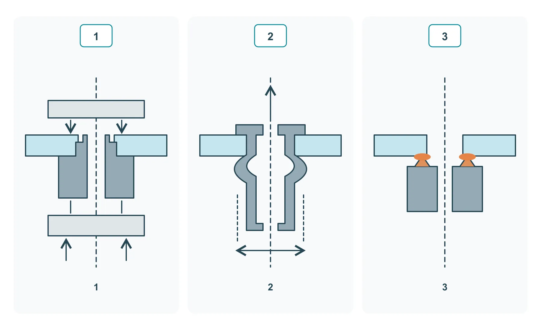
The first decision is how the enclosure will be assembled and serviced. A self-clinching nut may suit a panel that can be reached by an installation press before bending, while a rivet nut can create a thread when only one side of the finished panel is accessible. A weld nut or stud may fit a heavier or welded assembly when heat, distortion and finish cleanup are acceptable in the manufacturing route.
The mating screw and service direction matter too. Ask whether the joint is assembled once at the factory, opened repeatedly for maintenance, used to mount a PCB, or loaded by a cover, bracket, rail or cable component. The answer guides hardware selection and inspection without turning the enclosure supplier into the owner of the product's structural validation.
- Confirm whether both sides of the sheet are accessible during hardware installation.
- Show whether the fastener is installed before or after bending and welding.
- Identify repeated service joints separately from one-time factory assembly.
- Provide mating screw, washer, bracket or board-stack details where fit is critical.
- Keep buyer-owned load and life requirements visible in the drawing or specification.
Use self-clinching nuts, studs and standoffs with compatible sheet
Self-clinching hardware, often described as PEM-style hardware, is pressed into a prepared hole so displaced sheet material flows into the fastener's retention feature. It can create clean threads, studs or board standoffs without a separate weld, but reliable installation depends on the approved hole, sheet thickness, sheet hardness, edge distance and press access.
Do not copy an insert from another project without checking the supplier data for the current sheet. A fastener intended for softer steel or aluminum may not install correctly in harder stainless material, and a hole that is too close to an edge or bend can distort during pressing. The drawing should call out the installation side because the visible head, projection and mating direction affect the assembly.
- Match hardware series to sheet material, hardness and minimum approved thickness.
- Use the hardware supplier's specified installation-hole size and tolerance.
- Check edge distance, hole spacing, bend clearance and press-tool access.
- Show head side, stud projection or standoff height from a clear datum.
- Protect threads and bearing faces through coating when required.
Catalog example: check PEM S-M3-1 before specifying it
In the PEM self-clinching nut catalog, S-M3-1 identifies a carbon-steel S-series nut with an M3 × 0.5 thread and shank code 1. Pages CL-4 and CL-5 specify steel or aluminum sheet at HRB 80 or less, a recommended minimum sheet thickness of 1.00 mm and a maximum shank length of 0.97 mm. The ordering finish suffix must also be agreed; this designation alone does not define the complete finish requirement.
The same metric row gives a mounting hole of 4.22 mm with +0.08/−0 tolerance: 4.22–4.30 mm. Its minimum hole-center-to-sheet-edge distance is 4.8 mm. That is a center distance, not the remaining metal from the hole edge; it also does not replace a separate check of bends, neighboring hardware and installation tooling.
For a teaching example, a sheet specified as 1.00 ± 0.10 mm can arrive at 0.90 mm, below that row's 1.00 mm minimum. Resolve the sheet tolerance or select another approved shank option before release. Compare actual material hardness as well. Catalog fit checks do not establish the installed joint's torque or pushout performance.
Use rivet nuts when one-sided installation is the key constraint
A rivet nut is inserted from one side and mechanically collapsed to grip the sheet. It is useful for closed sections, already formed panels or large enclosures where the back side cannot support self-clinching installation. Body shape, grip range, flange style and installation-hole geometry all influence spin resistance, pull-through behavior and the finished appearance.
Because the installation process deforms the rivet nut rather than the surrounding sheet into a clinch feature, the RFQ should specify the exact or approved hardware and the intended sheet stack. If the joint will be serviced repeatedly or exposed to meaningful torque, state the buyer's acceptance requirement and how it should be checked on samples.
- Confirm one-sided tool access and clearance behind the collapsed body.
- Match grip range to the finished sheet or panel stack.
- Specify round, keyed or shaped installation holes only from approved hardware data.
- Define head visibility, projection and cosmetic expectations.
- Include spin, fit or torque checks when the product specification requires them.
Plan weld nuts and studs around heat, distortion and finish
Weld nuts and studs can provide threaded or locating features in fabricated enclosures, frames and chassis assemblies. They may be chosen when the joint layout fits the welding route or when the specified hardware is designed for welded attachment. However, welding introduces heat, possible distortion, weld marks, spatter and cleanup requirements that must be considered before surface finishing.
Show the weld side, hardware orientation, position tolerance and any no-weld or cosmetic zones. If electrical continuity or grounding is required, identify the buyer's contact requirement and masking plan. The supplier can control the documented welding and inspection route, while product-level strength, grounding and durability remain subject to the buyer's defined validation.
- Identify weld nut or stud type, orientation and projection.
- Mark cosmetic faces, heat-sensitive features and nearby bends.
- Define weld cleanup, spatter control and pre-finish inspection needs.
- Show conductive or grounding interfaces that must remain functional.
- Confirm final thread protection and gauge checks after finishing.
Coordinate holes, bends, installation and coating sequence
Fastener problems often begin in the flat pattern. A hardware hole too close to a bend, edge, louver or neighboring insert may distort during forming or leave no room for installation tooling. A fastener installed too early can block a bend tool, while one installed too late may be impossible to reach inside a closed chassis.
Surface finishing adds another sequence decision. Powder coating or paint can build up on threads, bearing faces and grounding zones; plating or passivation may impose different cleaning and material-compatibility requirements. The controlled drawing should show which areas are masked, plugged, protected or checked after finishing.
For this catalog's self-clinching installation, prepare the specified hole without a secondary countersink or deburring operation that removes retaining metal, and squeeze with parallel punch and anvil faces until the shoulder seats. See CL-10 and CL-18; determine the installation setting on the actual sheet. Keep this hole-preparation instruction separate from deburring other enclosure edges.
- Review flat-pattern hole-to-bend and hole-to-edge relationships before release.
- Confirm whether installation occurs in the flat, partly formed or fully formed condition.
- Keep press anvils, rivet tools and welding heads clear of flanges and returns.
- Mark masked threads, grounding pads, sliding faces and cosmetic surfaces.
- Recheck cover fit, mating hardware and enclosure alignment after the full finish route.
Approve hardware with risk-based sample and inspection checks
A visual check alone may not confirm that enclosure hardware is suitable. First articles should verify location, projection, perpendicularity, thread condition, head seating, sheet deformation, finish coverage and mating-part fit. Critical fasteners can also be checked using buyer-defined torque, pushout, pullout or functional assembly tests when the project requires them.
Keep those checks proportional to risk. A PCB standoff, removable service-panel nut and cosmetic rivet may need different approval evidence. Record the approved hardware source, drawing revision and sample result so repeat production does not drift to an unreviewed substitute.
- Measure critical location and projection from the specified datum.
- Inspect sheet cracking, panel distortion, head seating and visible marks.
- Gauge threads after installation and again after finishing where needed.
- Use the actual mating part or assembly fixture for critical fit checks.
- Require written approval before changing hardware type or supplier.
Final enclosure hardware RFQ checklist
A complete hardware RFQ makes the manufacturing order visible: create the hole, form the panel, install or weld the hardware, finish the enclosure, protect functional areas and inspect the final assembly. Use the following checklist before requesting a quote for an enclosure, chassis, cover or panel with installed hardware.
- Hardware identity: type, part number, thread, quantity and approved alternatives.
- Sheet input: material, thickness, temper or hardness and finish condition.
- Geometry: hole, datum, edge and bend relationships plus installation direction.
- Process order: cutting, forming, installation, welding, finishing and assembly.
- Functional notes: access, mating parts, grounding, masking and service conditions.
- Approval notes: samples, visual checks, thread gauges, buyer tests, records and packaging.
| Hardware family | When it may fit | RFQ details to define |
|---|---|---|
| Self-clinching nut | Clean reusable thread with press access before the enclosure closes | Approved series, sheet compatibility, hole, installation side, thread and post-finish check |
| Self-clinching stud | Fixed threaded projection for brackets, covers or internal assemblies | Projection, datum, orientation, mating stack, press access and thread protection |
| Self-clinching standoff | PCB or internal component spacing with controlled installed height | Standoff height, thread, board reference, location, perpendicularity and fit check |
| Rivet nut | One-sided thread installation in formed or closed panels | Grip range, body and head style, hole, access, projection and buyer-required spin or torque check |
| Weld nut | Threaded feature integrated into a welded enclosure or frame route | Nut type, weld side, position, heat and distortion notes, cleanup, finish and thread gauge |
| Weld stud | Fixed locating or mounting stud where the welded route is acceptable | Stud projection, location, weld access, cosmetic side, finish protection and buyer validation |
| Solid or blind rivet | Permanent panel, bracket or label attachment without a reusable thread | Rivet type, material stack, installation side, head appearance, access and assembly inspection |