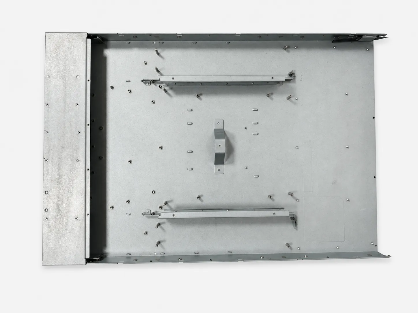
A useful enclosure drawing coordinates mechanical structure, electronics interfaces, assembly, finishing and product validation. Outside dimensions alone do not tell a fabricator which faces are cosmetic, which joints must remain conductive, how a cover is serviced, where a gasket seals, or which dimensions control connector and board alignment.
This guide separates supplier DFM from system engineering. A sheet metal supplier can review cutting, bending, hardware insertion, welding, finishing and inspection; the buyer and responsible engineering team remain responsible for loads, electrical safety, ingress, EMC, thermal performance and any certification required for the finished product.
Design inputs
Begin with a controlled input sheet: maximum product envelope, board and connector locations, mounting method, service direction, internal keep-out zones, cable entry, expected loads, installation environment, appearance surfaces and planned production quantity. Identify the datums that locate boards, rails, doors, displays and mating equipment so the drawing controls function rather than every non-critical edge.
Assign ownership for each performance requirement. The buyer should state the required environment, thermal load, EMC objective, electrical bonding scheme and applicable market or installation standard. The fabricator can propose manufacturable seams, vents, brackets, hardware and finishes, but should not be asked to infer system-level safety or certification from a mechanical model.
- Provide a revision-controlled 2D drawing and STEP/STP assembly with the same geometry and revision.
- Mark critical interfaces, mating parts, connector windows, PCB standoffs and cable bend space.
- Identify cosmetic faces, service panels, lifting or mounting loads and prohibited weld or tool-mark zones.
- Separate fixed requirements from dimensions, materials or features that are open to supplier DFM.
Material and thickness
Cold-rolled steel offers economical stiffness and magnetic shielding but normally needs a protective finish. Zinc-coated steel can improve corrosion resistance, although cut edges, welding and cosmetic finishing need review. Stainless steel suits wet, corrosive or hygienic service at higher forming and material cost. Aluminum reduces weight, resists corrosion and conducts heat well; 5052 is commonly chosen for formed enclosures, while harder grades and tempers may need larger bend radii.
Select thickness from panel span, load path, dent resistance, fastener engagement, flatness, weight and process capability rather than from product size alone. Return flanges, hems, beads, ribs and internal rails may add stiffness more efficiently than simply increasing gauge. Confirm actual grade, temper, grain direction, mill tolerance, available stock and finish route before design release.
Bending and cutout DFM
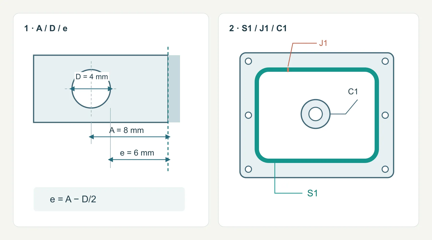
Define the dimensions before applying a spacing rule. T is sheet thickness, R is the inside bend radius, A is the perpendicular distance from a circular hole centre to the bend tangent on the flat face, and D is the hole diameter. The nearest hole-edge clearance is e = A − D/2. Do not confuse this with a distance to the theoretical sharp corner or the outside of the formed wall.
Geometry example: A = 8 mm and D = 4 mm give e = 6 mm. This describes the drawing; it is not a recommended minimum. Whether the hole will distort depends on the material grade and temper, thickness, bend radius, die opening, bend direction and sequence. Show which opening must align with a connector so the supplier can assess the actual fit requirement.
Confirm bend allowance or bend deduction with the intended process. Review holes, slots and ventilation patterns in the formed state, including welding and coating effects. Moving a cutout, adding relief or making a critical opening after forming are possible responses; select them with the supplier before releasing the drawing.
- State the inside bend radius and material condition; review cracking and springback on representative material.
- Dimension hole-to-bend clearance to the bend tangent and hole-to-edge clearance to the actual cut edge.
- Show bend relief geometry and check that the end of the bend can deform without tearing the adjacent wall.
- Check flange length, tooling access and opposing bends against the intended forming sequence.
Hardware, welding and assembly
Select threaded features by service load, access and expected assembly cycles. Self-clinching nuts, studs and standoffs can provide repeatable threads in thin sheet, but they need installation-tool clearance, suitable material hardness, correct edge and bend spacing, and a defined installation direction. Tapped holes, rivet nuts, weld nuts and loose fasteners may fit other thicknesses or service conditions.
Choose joints from structural, cosmetic, sealing and distortion requirements. Tabs, rivets and screws simplify service; spot or stitch welds limit heat input; continuous welds may support a sealed seam but can distort large panels and still require project-specific leak or ingress validation. Define the assembly sequence before placing hardware, closed corners or inaccessible fasteners.
- List manufacturer and part number for PEM or equivalent hardware, including allowed substitutions.
- Show installation direction, press access, minimum pull-out or torque requirements and post-install inspection.
- Mark weld type, length, location, cosmetic grinding and prohibited heat-affected surfaces on the drawing.
- Build a fastener and coating stack-up around hinges, doors, rails, connector panels and removable covers.
- Use common assembly datums so fabricated panels can be inspected before the full product is available.
IP, NEMA and UL
IEC 60529 classifies enclosure protection using IP codes. NEMA enclosure types include environmental conditions beyond an IP designation: NEMA explicitly says its comparison table cannot be used to convert an IP code into a NEMA type. Specify the required system and test conditions rather than treating labels as equivalents. [1, 2]
UL 50 covers non-environmental enclosure considerations; UL 50E adds environmental construction and performance requirements. The public UL catalog checked on 2026-09-14 lists UL 50E Edition 3 as active, published 2020-10-15 and revised 2025-10-17. The catalog scope and revision summary were reviewed; the project must use the applicable full standard and end-product requirements. [3]
A claim concerns the defined assembled configuration. Record the shell revision, door, gasket, latches, cable entries, vents, coating and installation orientation, then assign evaluation or testing to the responsible party. A tested cable gland does not establish the rating of the enclosure around it.
Sealing, thermal management and EMI
Trace the seal as one closed loop, shown as S1 in the teaching diagram. At each corner, gasket joint, fastener and cable entry, ask whether water can cross into the protected volume. A cover screw outside the loop and a hole through the loop create different paths. Define gasket compression from the selected seal supplier’s data, and check the assembled gap and door deflection; an outline on CAD does not confirm compression.
Design the sealing path as a continuous system. Define the gasket material and joint, compression target, corner treatment, door stiffness, latch or screw pattern, gland interfaces, drain strategy and service life. Powder coating on a sealing land, weld distortion or a poorly supported door can break the path even when the nominal enclosure shape looks correct.
Build thermal decisions from a heat-load and ambient-temperature model. Place intake and exhaust openings around the actual component layout, keep recirculation paths visible, and specify fans, filters, heat sinks or conductive interfaces as buyer-controlled components. Passive slots and louvers reduce sealing and may weaken panels; dense perforation can also cause flatness problems.
Treat EMI as a seam-and-opening problem, not simply a material choice. Define bonding points, masking, conductive finishes, finger stock or shielding gaskets, vent geometry and cable entry treatment. Sealing, airflow and EMI commonly pull the design in different directions, so validate the combined configuration instead of optimizing each requirement separately.
- Map the complete gasket and conductive-contact paths on the assembly drawing.
- Provide heat dissipation, ambient limits, airflow direction and component keep-out zones.
- Mark paint-free grounding points, masked threads and coating-sensitive sliding or contact surfaces.
- Assign ingress, thermal and EMC tests to the responsible qualified lab or engineering team.
Prototype validation
Use prototypes to close assumptions before repeat production. Inspect outside dimensions, functional datums, connector alignment, door and cover fit, hardware position, weld distortion, coating buildup, cosmetic surfaces and packaging protection. Record every accepted DFM change in updated 2D and 3D files rather than relying on email exceptions or an unmarked sample.
Mechanical first-article approval is not a substitute for product validation. If the project requires ingress, thermal, EMC, grounding, vibration, corrosion or safety testing, test the representative assembled product with production-intent gaskets, hardware, finishes, cable entries and vents. Link test results and the approved sample to the same drawing revision used for the production quote.
- Agree prototype quantity, sample lead time and production-intent processes before ordering.
- Create a first-article checklist around critical-to-fit and critical-to-function dimensions.
- Approve hardware, finish color and texture, masking, labels and cosmetic workmanship.
- Run required system tests with representative components and installation conditions.
- Freeze the approved revision, inspection plan and packaging standard before mass production.
RFQ checklist
A quote-ready enclosure package lets engineering, purchasing, quality and the supplier review the same scope. Include enough product context to expose risk without asking the fabricator to certify performance outside its role.
- Controlled 2D drawings, STEP/STP assembly and flat files only when the buyer controls the flat pattern.
- Material grade, temper where relevant, nominal thickness and allowed alternatives.
- Quantity bands, prototype and annual demand, target schedule and expected program life.
- Critical datums, mating interfaces, cutouts, service access and cosmetic faces.
- Hardware schedule, weld and joint notes, finish, color, texture, marking and masking.
- Required IP, NEMA, UL or other target with edition, responsible party and validation plan.
- Thermal load, airflow, EMI, grounding, gasket and cable-entry requirements supplied by the buyer.
- Sample approval, inspection records, compliance documents, packaging and revision-control expectations.
| Decision | Practical starting point | Main trade-off | Confirm before release |
|---|---|---|---|
| Cold-rolled steel | Use where economical stiffness and magnetic shielding matter | Requires corrosion-protective finish | Grade, thickness, coating, weld and grounding plan |
| Zinc-coated steel | Use where added corrosion protection is useful | Cut edges, welding and cosmetics need review | Coating type, edge treatment and finish adhesion |
| Stainless steel | Use for wet, corrosive or hygienic environments | Higher cost and forming force; springback | Grade, surface condition, grain and bend tooling |
| 5052 aluminum | Use for formed lightweight enclosures and heat spreading | Lower stiffness than steel at equal thickness | Temper, grain direction, radius and anodizing plan |
| Inside bend radius | Specify R and the actual grade/temper | Tight bends may crack; springback changes fit | Material, tooling, bend direction and trial result |
| Hole near bend | Measure A to tangent, then e = A − D/2 | Edge clearance and centre distance are different | Cutout function, die opening and operation sequence |
| Self-clinching hardware | Use when repeatable threads are needed in thin sheet | Requires material and installation-tool compatibility | Part number, access, spacing and performance test |
| Sealed or shielded seam | Define the complete gasket or conductive path | Sealing, airflow, EMI and service access conflict | Assembly-level test method and responsible party |