Electrocoating uses an electric field to deposit charged paint from a waterborne bath onto a conductive part. It is useful for complex metal parts requiring continuous protection that can be immersed, but selection must address the coating system, pretreatment, cavity filling and venting, finished fits and cure conditions together. Inspect critical locations on actual parts; appearance, average thickness or one salt-fog report is insufficient. [1][5][6][7]
What coating does electrocoating produce?
Industrial electrocoating is also called electrodeposition painting or e-coat; cathodic systems may be called CED, cataphoresis or KTL. This guide concerns organic paint films on metal parts. Electrophoretic deposition also serves ceramics, biomaterials and other systems, whose formulations and processes cannot simply be transferred to enclosure corrosion protection. [1][5][7]
Electrocoating and electroplating both use current and a bath, but produce different layers. Electroplating usually deposits metals or alloys; the e-coat discussed here is an organic coating based on resin. It also differs from anodic oxide and conversion layers formed during pretreatment, such as phosphating. [1][6][7]
“E-coat” identifies the application method without specifying resin or use. “Cathodic epoxy e-coat primer” and “cathodic acrylic e-coat finish” are more complete descriptions: the former commonly provides corrosion-protective priming, while the latter can be evaluated for weathering and decorative requirements by product. Once coated, the part does not need an external power supply to maintain protection; the word “cathodic” does not make ordinary e-coat a sacrificial coating like zinc. [6][7]
Why does paint deposit, then slow down locally?
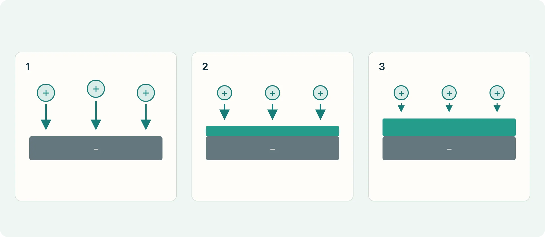
Two conditions must hold: the part must maintain a reliable electrical connection to the rectifier, and charged paint must reach its surface through the bath under the electric field. Immersion alone does not ensure an acceptable electrodeposited film. [5][6][7]
In cathodic e-coat, the part is negative and paint particles are positively charged. After migration toward the part, electrochemical neutralization and film formation occur near its surface, turning dispersed resin into a deposited film. Migration, interfacial reactions and film formation all matter; “opposite charges attract” is not the complete explanation. [5][7]
Film forms first at electrically accessible locations. As it thickens, resistance to current rises locally, deposition slows and current distribution changes. This helps deposition continue on less accessible bare regions. It gives a self-limiting tendency, without guaranteeing identical thickness everywhere at the same time. [1][6][7]
Final thickness depends on the voltage profile, time under power, bath condition, geometry and cured film. Higher voltage may increase deposition, but some substrate/coating combinations can develop local gas, heating and film rupture. Particularly on galvanized surfaces, a thin internal film is not an automatic instruction to raise voltage throughout the bath. [1][5][8]
First confirm electrical connection and liquid access; then review position-specific measurements and process records; finally trial adjustments within the coating's permitted window. This sequence matters especially when exterior thickness is adequate but cavities remain thin.
How do polarity and resin classifications differ?
Electrical polarity and resin selection are different classification dimensions. The part is negative in cathodic deposition and positive in anodic deposition. Anodic processes can introduce substrate metal ions into the film, affecting corrosion performance in some systems; cathodic systems reduce this incorporation and are widely used for protective primers. [1][7]
“Cathodic” does not itself mean “outdoor finish.” Common aromatic epoxy systems offer useful corrosion and chemical protection, but sunlight exposure still requires evaluation of chalking, discoloration and a subsequent topcoat. Weathering of the resin, pigments and complete system must be checked separately. [6][7]
| Candidate system | Uses to discuss first | Conditions to confirm |
|---|---|---|
| Cathodic epoxy e-coat | Protective primers on steel structures, brackets and enclosures; single-layer non-sunlight uses within product suitability | Pretreatment, edge/cavity thickness, curing and mechanical exposure; compatible topcoat for sunlight |
| Cathodic acrylic e-coat | Single-layer or combined systems requiring color/gloss retention and UV resistance | Specific color, gloss, weathering, corrosion requirements and cure conditions |
| Anodic epoxy or acrylic | Some decorative, indoor or product-specific curing applications | Substrate–film interaction, intended use and corrosion requirements; verify low-temperature capability by product |
| E-coat primer plus liquid or powder topcoat | Parts requiring internal protection together with external color and weathering performance | Primer/topcoat compatibility, recoating conditions, total thickness, both thermal cycles and finished fits |
These are candidate uses, not corrosion or cost rankings. Products in the same category can have different curing windows and performance. For UV protection, special colors or low-temperature cure, obtain the specific product's technical data sheet rather than specifying only “e-coat paint.” [6][7]
Why does throwpower not guarantee every cavity is coated?
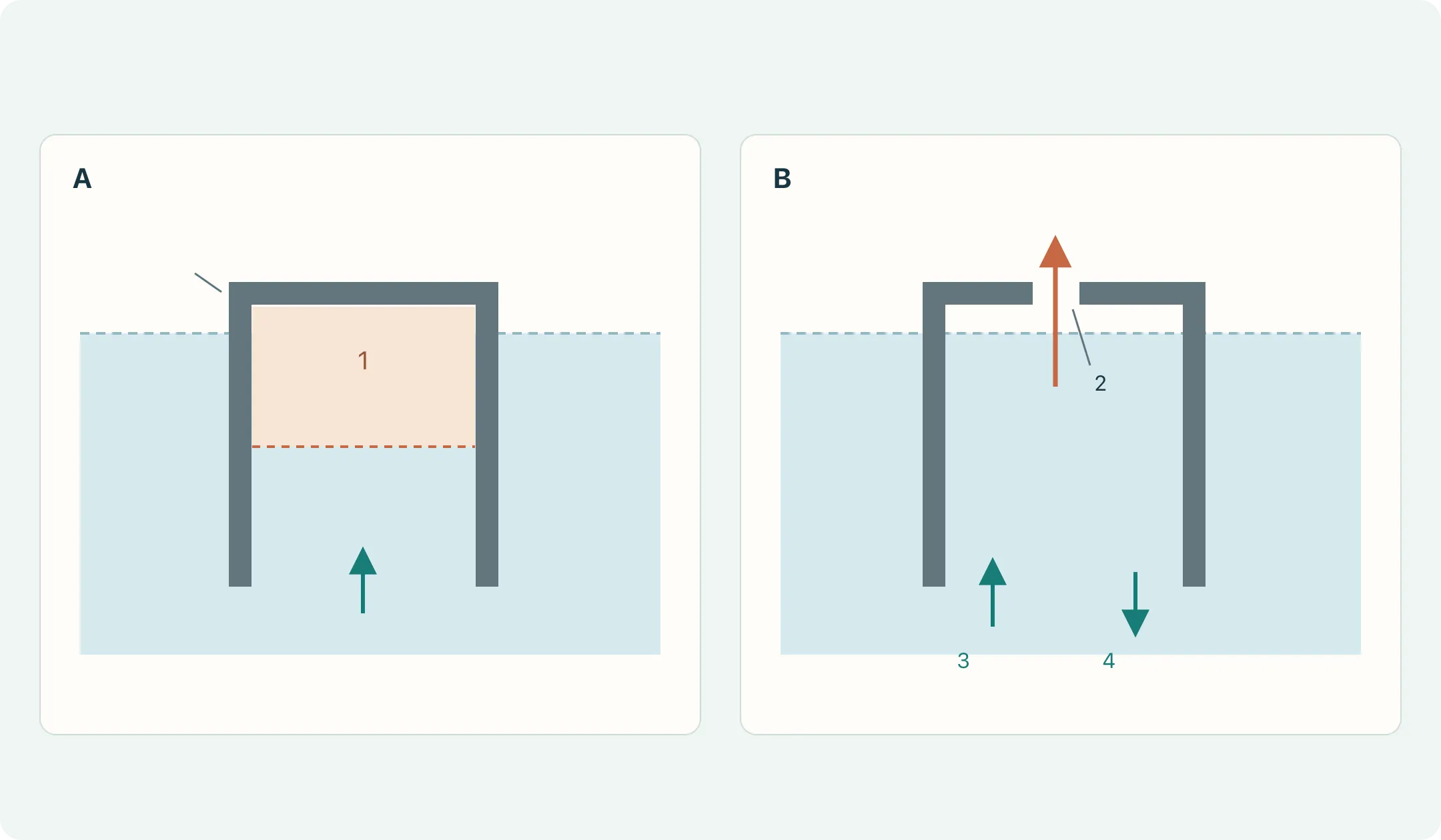
Throwpower describes deposition into recessed, shielded and internal regions. The film formed first externally raises local resistance and helps redistribute current toward other accessible locations, an important reason e-coat suits complex parts. [7]
At least three limits remain: whether bath liquid contacts the surface, whether current has an effective path, and whether entering/leaving liquid and air can flow. A filled cavity does not guarantee target thickness at its bottom; full exterior coverage does not establish coverage inside a closed lap joint. [5][7]
Check five locations in the part geometry
- Pockets and inverted spaces. Check trapped air in the actual immersion orientation. Gas-isolated surfaces cannot contact the bath normally; assess reorientation, a vent path or geometry changes.
- Deep holes, blind holes and narrow gaps. Check entry and exit separately for pretreatment solution, paint bath and rinse water. Exterior readings cannot replace coverage checks at hole bottoms or within gaps.
- Folds, laps and welds. Look for closed layers, oil, weld residues and liquid-retaining gaps. Tightly closed interfaces without bath access cannot be corrected by throwpower.
- Fixture contacts. Ensure reliable electrical contact and define permitted fixture shadowing/contact marks. Contacts on appearance-critical or protective regions can complicate repair and acceptance.
- Liquid-retaining regions after withdrawal. Liquid held in cavities or recesses may escape during later handling/heating and cause defects or contamination. Review filling and drainage together. [2][5][8]
For a steel enclosure with folds and weld nuts, identify the visible large face, inside folds, hole bottoms and laps separately. Agree orientation with the coater, then inspect actual-geometry samples at those locations; provide dismantlable, sectioned or witness features when needed. More flat coupons alone cannot establish acceptance of shielded cavities.
Vent and drain holes have no universal minimum diameter. Their positions also affect strength, sealing, water resistance and appearance; select them with geometry, flow paths and use requirements. Coating convenience should not compromise the product's sealing design.
Pretreatment determines the condition below the paint
E-coat deposits paint without automatically removing stamping oil, rust, cut-edge oxides or welding residues. Pretreatment prepares the actual substrate for the coating, establishes an acceptable interface and limits contamination carried into the paint bath. [1][2][8]
Typical steps include cleaning, rinsing, surface conditioning/conversion treatment and further rinsing, followed by e-coat, post-rinsing and curing. The actual sequence depends on substrate, pretreatment chemistry, coating and required performance; not every project uses the same phosphating line. [1][6][7]
| Substrate or location | First checks | Why it needs separate attention |
|---|---|---|
| Carbon steel and cold-rolled steel | Stamping oil, rust, cut-edge oxides, weld residues and compatible conversion treatment | Cleanliness and roughness affect film uniformity, interfacial bonding and later protection |
| Galvanized steel or zinc-coated parts | Zinc condition, existing passivation/anti-fingerprint treatment, white rust and cleaning compatibility | The surface differs from bare steel; aggressive cleaning, incompatibility or overly rapid energization can cause problems |
| Aluminum or aluminum/steel assemblies | Alloy/oxide condition, mixed-substrate pretreatment compatibility and trapped-liquid locations after assembly | Conductivity alone does not establish compatibility with a steel-parts coating line; confirm the actual material combination |
| Stainless steel, copper and other metals | Actual material, existing surface treatment and coating compatibility | A material being electrocoatable does not mean every line can process it under the same conditions |
| Roughened areas, burrs, welds and cut edges | Roughness, particle residues, cleanliness and edge coverage | Roughening is not degreasing; protrusions and gaps can create thin-film or contamination sites |
These checks follow industrial process and surface-quality analysis across substrates; confirm them with compatible material data and actual samples. [1][2][6][8]
Rougher surfaces are not necessarily better for e-coat. A comparison on S355J2G3 steel rails using a specified paint found different film uniformity and structure after chemical cleaning versus abrasive blasting alone. It shows pretreatment changes deposition; it does not establish that pickling always outperforms blasting or justify copying the cleaning formulation. [2]
Evaluate oil removal, residual contamination, surface condition, and the final coating's adhesion and exposure performance together. When bath abnormalities appear, also trace rinsing and contamination carried in from earlier stages. [1][8]
What do bath control and ultrafiltration each accomplish?
Stable production relies on connected conditions: formulation, bath temperature, pH, conductivity, contamination, circulation/filtration, rectifier supply and post-rinsing. Manage them within the specified coating/equipment process window. [1][5][8]
| Item | What it helps determine | Actions to avoid adopting automatically |
|---|---|---|
| Solids, pigment-to-binder ratio and specified formulation checks | Whether effective film-forming material and composition remain stable | Adding paint simply because film is thin, ignoring water, contamination and formulation balance |
| pH and conductivity | Chemical drift, ionic carry-in and electrical deposition conditions | Treating them as the same measure or adjusting formulation by conductivity alone |
| Temperature, circulation and filtration | Uniformity, sediment, particles and local differences | Assuming more heat, circulation or finer filtration is a universal remedy |
| Voltage, current and time profiles | Contact problems, overly rapid deposition or supply fluctuation | Recording final voltage alone without ramp and current changes |
| Pre/post-rinses and ultrafiltration loop | Control of contamination carry-in, paint drag-out and post-rinsing | Assuming ultrafiltration automatically removes all contamination |
The same final voltage can give different local thickness and appearance with different ramps, loading densities or bath conditions. Records should identify how the batch was hung, energized and processed in the bath at that time. [5][8]
Ultrafiltration separates permeate usable for recovery rinsing while retaining paint solids in the bath. Parts carry out undeposited paint as well as deposited film; post-rinses remove the former and recover it according to circuit design. This can improve material use and appearance but is not a universal purifier for dissolved contaminants. [1][6][7]
For abnormalities, compare pH, conductivity, solids, pretreatment carry-in, post-rinses and ultrafiltration records before the paint supplier specifies corrective action. Without the system and contamination source, do not adopt a universal acid/alkali dose, bleed fraction or replenishment recipe.
Waterborne does not mean emission-free. Formulations may contain co-solvents and curing can release volatile substances. Include cleaning, rinsing, bath maintenance and wastewater treatment in process and cost assessment. [7]
Cure acceptance depends on the actual part's temperature history
Completed deposition and completed chemical cure are separate stages. Post-rinsing removes dragged-out paint; heating then allows the selected thermoset system to flow, dry and crosslink. A continuous film at withdrawal does not establish required mechanical/protective performance. [1][4][6]
Check whether the technical data sheet specifies curing time at actual part temperature. Where time is based on part temperature, verify effective time after the part reaches the required temperature; oven setpoint or total oven residence cannot directly replace it.
Thick brackets, thin lids, welded reinforcements and different oven locations can heat differently. Cover representative positions with temperature measurements, retain curves and compare with the product window. Reconfirm after changes in thickness, loading density or line speed.
Trials varying cure time and temperature for specified steel and e-coat observed changes in adhesion and impact behavior. Thickness and appearance therefore cannot replace cure/mechanical checks; a study's optimal temperature cannot be transferred to another product. [4]
Assemblies with rubber, plastics, adhesives or precision components need compatibility checks through pretreatment immersion, e-coat and every baking step. For later powder/liquid topcoats, evaluate the second heat cycle and primer/topcoat compatibility together. [6][7]
An appropriate solvent rub assesses solvent resistance under specified conditions; solvent, rub count and criteria depend on the chosen method and coating requirements. A particular solvent-resistance level alone still does not prove complete cure. [11]
How does thickness affect holes, threads and electrical contacts?
E-coat is an added layer. Film deposited on bore walls, threads, locating/sealing surfaces and sliding clearances can change finished fits. Thickness-control advantages do not eliminate dimensional effects. [6][7]
Calculation example: assume an initial round-hole diameter of 6.000 mm and actual cured films t₁ = 0.020 mm and t₂ = 0.018 mm on opposite walls. Neglecting other dimensional changes, the finished diameter is approximately:
D_after = D_before − t₁ − t₂ = 6.000 − 0.020 − 0.018 = 5.962 mm.
The example adds the space occupied on both sides; these are not recommended e-coat thicknesses. Deposition and measurement access in a real bore may differ from a flat surface. Check finished dimensions and fit rather than substituting an exterior nominal reading for bore-wall thickness.
Thread fit cannot be judged from this round-hole formula alone. Accept threads using finished requirements, gauges or actual assembly, then assess masking, operation sequence and rework. If rework cuts the coating, address protection at the exposed locations.
Ordinary e-coat should not be assumed to provide reliable conductive contacts. Specify uncoated or specially treated grounding, shielding joints and contacts; verify the electrical path in the final tightened assembly. Do not assume screws will consistently pierce the film; exposed contacts also need environmental protection.
How should investigation of bare areas, pinholes or peeling begin?
Describe the observation and location before choosing validation methods. Pinholes, craters, particles, blisters and bare regions can arise at different stages; a photo alone cannot establish root cause. Especially on galvanized parts, substrate, pretreatment, bath, electrical profile and baking can all affect appearance. [8]
| Observation | First investigation directions | Useful comparison or verification |
|---|---|---|
| Large local bare areas or very thin film | Fixture electrical contact, shadowing, trapped air, bath access and current accessibility | Measure by position; compare orientation; inspect contacts and representative opened cavities |
| Adequate main face but thin folds/deep regions | Geometry paths, throwpower, fixturing and electrode position | Compare internal/external thickness on the same part after changes, rather than only an overall average |
| Pinholes, local rupture or rough protrusions | Substrate/pretreatment, voltage profile, local gas/heating, bath and cure | Microscopy and comparison with normal parts and electrical, bath and thermal records |
| Craters, depressions or particles | Oil/other contamination, pretreatment residues, circulation/filtration, handling and oven contamination | Observe by process stage and inspect particles/failure locations; not every depression is electrical rupture |
| Water marks, drip marks or local appearance variation | Rinsing, retained liquid, orientation, withdrawal drips and baking | Compare before/after oven entry; inspect liquid-retention paths and rinse records |
| Blistering, peeling or assembly-related chipping | Cleanliness/interface, cure, intercoat compatibility, edge coverage, residues and mechanical action | Retain failed parts; identify the separation layer; compare before/after assembly and specified exposure |
This table proposes directions to verify; defects and causes do not have a one-to-one mapping. [1][2][4][5][8]
Retain unrepaired failed parts and normal controls; record material, paint, orientation, detection stage and rework history. Changing several stages without records makes it difficult to identify which change improved results.
Compatible touch-up may address local mechanical damage; widespread interface failure should not simply be painted over. Re-electrocoating depends on old-film resistance, stripping, substrate condition and later heating. Establish a rework route and validate actual parts; cured paint is not the same deposition surface as bare metal. [2][6][7]
Specify inspection locations, methods and acceptance criteria together
E-coat quality includes coverage, thickness, appearance, curing, adhesion, mechanical exposure, environmental protection and assembly function. These answer different questions and must be selected by use, rather than substituted for one another. [2][4][5]
For a steel enclosure, identify M1 visible large face, M2 inside fold, M3 near weld/lap, M4 inspectable bore and M5 near fixture contact; check grounding and sealing separately for function. Numbering connects drawings, measurements and failure photos to the same locations; it does not prescribe one universal number of measurements.
| What to confirm | Inspection arrangement | Information to retain |
|---|---|---|
| Critical-location coverage and thickness | Select thickness method by substrate, curvature and access; section/open cavities when needed | Location map, calibration, individual readings and local criteria; identify layer or total thickness in multilayers |
| Appearance and defects | Agreed lighting, viewing distance and visible-surface conditions | Approved color panel/sample, color/gloss requirements, contacts and permitted defect positions/severity |
| Curing | Compare actual-part temperature history with product data and necessary performance checks | Product, curves, measurement locations and decision; record solvent-resistance method separately |
| Adhesion behavior | Choose applicable cross-cut, tape-cut or other method | Standard/edition, thickness, specimen state, position, rating and separation layer |
| Mechanical and assembly behavior | Impact, bending, fastening or actual assembly checks selected by use | Loading/assembly conditions, crack/peel positions, finished dimensions and contacts |
| Corrosion and environmental protection | Agreed salt fog, damp heat, cyclic corrosion or use-related exposure | Substrate, pretreatment, complete coating, specimen state, exposure and blistering/rust/scribe-creep criteria |
Adhesion ratings are not interfacial strength values
ASTM D3359 tape tests assess adhesion under specified conditions, without measuring an absolute interfacial failure force or finely distinguishing very high adhesion. Humidity, temperature, tape and operation affect results. Multilayer separation can be between coats, without testing the lowest layer's metal bond. [9]
ISO 2409 and ASTM D3359 procedures or ratings cannot be interchanged simply because both are called cross-cut tests. Identify the method/conditions in reports. Confirm applicability on small curved, recessed or narrow areas; informal cuts where the standard cannot be performed do not establish a passing result. [9]
Salt-fog hours are not outdoor years
Salt fog compares specified specimens in a controlled environment, but ASTM B117 does not automatically set product duration or acceptance criteria. Salt-fog results alone generally do not predict natural-environment service life. [10]
E-coat and zinc layers differ in protection mechanism, thickness, pretreatment and damage behavior. A comparison on S235JR bus-door bracket material used e-coat/zinc coatings of different thicknesses and examined mechanical damage and salt fog. Compare actual exposure and complete systems; it cannot establish that e-coat always resists corrosion better than plating, or a universal reverse ranking. [3]
If stone impact, standing salt water or repeated wet/dry exposure is expected, make specimens, pre-damage and exposure reflect those factors. Align scribing, edge sealing, subsequent topcoat and permitted corrosion locations in comparative reports.
An acceptable average does not mean every location passes
Check each location against requirements before averages, dispersion, fixture-position differences and cross-batch trends. Mean thickness can hide a thin internal corner and thick exterior. A stable process can also remain consistently outside requirements. [5]
For Cp/Cpk reports, confirm the measurement system, data grouping, stability and distribution assumptions. Fixed locations, multiple parts and time information in a steel charging-station enclosure study support keeping that information, but thickness statistics do not establish salt-fog, adhesion or service-life performance. [5]
How should you decide whether to use e-coat?
Consider e-coat first when parts are conductive and immersible, multiple internal/external areas need continuous coverage, thickness/batch consistency matters, and fixturing, pretreatment and cure suit the actual part. It is especially useful as a protective-primer candidate on complex metal parts. [6][7]
| Dimension | Electrocoating | Liquid spraying | Common thermoset powder coating |
|---|---|---|---|
| Application route | Immersion/electrical deposition requiring bath access and effective electrical connection | Liquid paint atomized toward the surface by conventional or electrostatic spray | Dry powder, commonly deposited electrostatically |
| Cavities and shielded locations | Throwpower helps, but trapped air, narrow gaps and retained liquid need validation | Depends on gun path, access and application method | Deep internal corners and shielded areas need specific deposition assessment |
| Color and changes | One bath usually runs a specified system/color; other colors may use a topcoat | Change according to equipment, paint and cleaning arrangements | Powder colors can change; cleaning, contamination and recovery affect cost |
| Thermal process and fits | Confirm product cure window, including possible later topcoat heating | Confirm drying or curing for the particular paint | Confirm part temperature/time for the powder |
| Performance and total cost | Compare pretreatment, resin, coverage, compatibility, inspection and cost per accepted part | Compare complete routes under equivalent finished-part requirements | Compare complete routes under equivalent finished-part requirements |
Application method alone does not determine corrosion, weathering, hardness or total cost. Have each candidate meet the same appearance/function requirements rather than comparing single-layer e-coat and finished powder coating by process name alone. [6][7]
For an inquiry, provide drawings/photos, material and existing surface, expected quantity, environment, cavities, visible faces, grounding, threads and fits. Mark undecided paint, thickness or tests “to be confirmed.” Then agree contacts, masking, topcoat, samples and acceptance; compare cost per accepted part including pretreatment, fixturing, curing, inspection, packaging and rework.
- [1] Akafuah et al. Evolution of the Automotive Body Coating Process—A Review, Coatings, 2016
- [2] Skotnicki and Jędrzejczyk The Comparative Analysis of the Coatings Deposited on the Automotive Parts by the Cataphoresis Method, Materials, 2021
- [3] Skotnicki and Jędrzejczyk Comparative Analysis of Coatings Applied for Anti-Corrosion Protection of Public Transport Vehicles’ Structural Parts, Materials, 2024
- [4] Peti et al. Integrated Performance and Capability Analysis of Anticorrosive Cathodic Electrodeposition Coatings: Effect of Polymerization Variables, Materials, 2025
- [5] Piroh et al. Process Capability Assessment and Surface Quality Monitoring in Cathodic Electrodeposition of S235JRC+N Electric-Charging Station, Materials, 2026
- [6] PPG E-Coat Process Specifics
- [7] Lisa Merlo What is Electrocoating?, Products Finishing, 2011
- [8] Jose Tirado How to Identify and Control Poor Ecoat Film Appearance, Products Finishing, 2017
- [9] ASTM D3359-23 Standard Test Methods for Rating Adhesion by Tape Test
- [10] ASTM B117-26 Standard Practice for Operating Salt Spray (Fog) Apparatus
- [11] ASTM D5402-19(2024) Standard Practice for Assessing the Solvent Resistance of Organic Coatings Using Solvent Rubs