An aluminum extrusion with a visible face, an enclosure with a ground connection, a bracket with a sliding bore and a facade exposed to years of sunlight each need a different finish plan. When you send us a drawing, mark what matters beyond the color: electrical contacts, dimensions that must fit after treatment, visible faces and acceptable rack locations. These details give us a practical starting point for discussing the finish.
Use the decision map: start with function, approve on samples
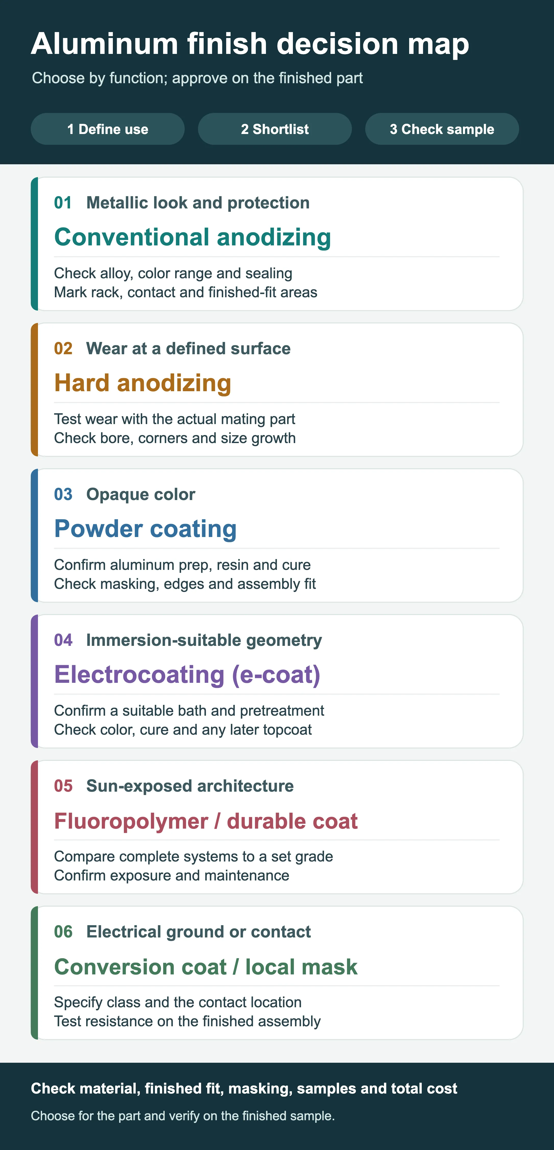
- 01–02: metallic appearance or wear at a defined surface. Start with conventional anodizing if the aluminum appearance should show; consider hard anodizing for a sliding contact with a stated wear duty. Check alloy and color range, rack marks, bore size and wear with the actual mating part. Thickness alone does not decide either route. [1][2][9]
- 03–04: opaque color or geometry suited to immersion. Powder and e-coat form organic films through different application methods. Confirm aluminum pretreatment, coating and cure, then check masking, edges, assembly fit and any later topcoat. For e-coat, confirm the available colors for the selected system. [4][6][8]
- 05–06: sun-exposed architecture or electrical contact. Compare complete coating systems against a stated weathering grade, including suitable liquid and powder options. For a ground connection, specify the contact-area treatment and measure resistance on the finished assembly. Fluoropolymer coatings and conversion coatings serve different functions. [3][7][8]
The six cards are starting routes, not mutually exclusive choices. An enclosure can have a cosmetic coating on visible faces and local masking or a specified treatment at a ground contact. Compare the finished fit, approved sample and total cost per accepted part before choosing. The table below gives the checks for each route. [2][3][4]
Mark five decisions on the drawing or a photo
- Where will the part work? Describe indoor or outdoor exposure, moisture, salt and named cleaning chemicals. A process name alone does not establish corrosion performance.
- Which faces are visible? Identify the desired metallic texture or opaque color, brushing direction, allowable rack locations and acceptable color range.
- Which surfaces must connect or fit? Circle ground and other electrical contacts, thermal interfaces, threads, bores, locating faces and sealing surfaces. Oxide and organic coatings can affect function or clearance there.
- What will rub? Distinguish handling marks and assembly scuffs from continuous sliding. “Hard” alone is not a wear specification.
- Which aluminum is it? Give the alloy, temper, product form, welds and earlier machining or forming. Anodizing can reveal differences in the substrate and welds. Where appearance matching matters, make range samples from representative material and processing. [1][2]
Separate the process names before comparing six common routes
Anodizing and chemical conversion coating describe how the surface forms. Powder coating and electrocoating describe how an organic coating is applied. “Fluorocarbon” usually describes the resin system: it may be a liquid finish, while high-performance fluoropolymer powders also exist. When comparing quotations, identify the actual resin, pretreatment and performance grade so each option covers the same requirements. [1][3][4][6][7][8]
Anodizing converts aluminum at the surface into an oxide. A chemical conversion coating forms through a reaction between treatment chemistry and the substrate. Powder, liquid and electrocoat systems add an organic film over a prepared surface. These mechanisms affect appearance, electrical behavior, dimensions and repair differently, so compare the complete finish against your part's service conditions. [1][2][3][4][6]
Brushing, blasting and polishing separately adjust texture, reflection or feel and often prepare the surface for one of these routes. They do not specify the final protection by themselves. Define the direction, roughness, cleaning and subsequent treatment. [1][2]
| Route | A reason to consider it | Confirm before approval |
|---|---|---|
| Conventional anodizing, such as sulfuric anodizing | Retain the aluminum appearance while adding a protective oxide; clear and dyed versions are possible | Alloy and preparation, color range, sealing, rack marks, fit and electrical contacts [1][2][9] |
| Hard anodizing | A defined surface needs an abrasion-resistant oxide, for example under representative sliding conditions | Coating thickness, actual wear duty, corners and bore coverage, and dimensions after treatment; the thickest coating is not automatically the best [2] |
| Powder coating | Opaque color or an organic coating selected for a specified weathering grade | Aluminum pretreatment, powder resin and pigment, cure, thickness, edge coverage, masking and finished fit [4][8] |
| Electrocoating or e-coat | A suitable aluminum part needs a deposited organic film from a coating bath, as primer or selected topcoat | Actual substrate and pretreatment, bath access, resin, available color, cure, any later topcoat and required environmental performance [6] |
| Fluoropolymer coating, such as architectural PVDF | A sun-exposed architectural panel or extrusion needs specified color, chalking and adhesion performance | Liquid or powder system, primer and topcoat, aluminum pretreatment, applicable standard, exposure and maintenance [7][8] |
| Chemical conversion coating | Corrosion protection, paint preparation, or a specified contact area requiring lower electrical resistance | Exact specification, type and class, subsequent paint, contact resistance under assembly conditions and corrosion checks [3] |
For a metallic look, start with anodizing and the substrate finish
Anodizing follows the underlying texture, so deep scratches and welds can remain visible. Surface preparation can change roughness, while alloy, material lot and welded areas can affect color. [1][2] If adjacent panels must match, use representative alloy and temper for approval samples, identify the visible faces and agree on an allowable color range. Send us photos to explain the appearance you want, then use physical samples to agree on color and texture.
“Clear” and “black” describe appearance, not a complete specification. Anodizing type, thickness, sealing and acceptance still need to be defined. [1][2]
For wear, evaluate hard anodizing with the actual mating part
Hard anodizing can provide a thicker, more wear-resistant oxide at a specified surface. To assess it for your part, state the mating material, lubrication, load, motion, permitted wear and inspection method, then compare representative samples. Type III coatings have a larger effect on dimensions, while intricate passages and sharp corners make uniform results harder. [2] Thin walls and precision bores need particular attention to actual geometry, racking and measurement locations.
For grounding or paint preparation, specify the contact and conversion-coat route
For a grounded enclosure, mark where the washer or other connector touches the part. Ordinary anodic oxide and organic coatings can interrupt that contact, so define local masking or a suitable contact-area treatment and measure resistance on the finished assembly. Where the applicable conversion-coating specification uses this classification, Class 3 addresses lower electrical resistance together with corrosion protection. Conversion coating can also provide a base for paint primer. Confirm the exact specification, treatment and contact pressure for your assembly. [3]
If your part requires a treatment without hexavalent chromium, include the applicable regulatory and product requirements with your drawing. Confirm that the selected chemistry meets those requirements and suits the intended corrosion protection, paint preparation or electrical-contact function. [3]
For color or outdoor weathering, compare the full coating system
Powder coating commonly applies charged powder and cures it according to the product specification. Liquid paint has its own application and curing conditions. [4] For aluminum, compare cleaning and pretreatment, coating chemistry, thickness range, masking, rack marks, the cure's effect on any assembled items and finished corrosion criteria. For exterior use, specify the exposure and weathering requirement along with the color. Suitable high-durability powder and architectural PVDF liquid systems can both meet demanding architectural coating grades. [7][8]
Degreasing and cleaning are part of preparation. Adhesion also depends on the remaining aluminum pretreatment steps, coating and cure, so include the required adhesion test and acceptance criteria in the finish specification. [4][6]
Electrocoating immerses a part in a paint bath and deposits an organic film using an electric field. Formulations can be primers or selected topcoats. An e-coat line normally runs a specified coating and color; a compatible liquid or powder topcoat can provide other colors where needed. Confirm aluminum compatibility, bath access, pretreatment, coating, cure and weathering requirements for the proposed system. [6]
Architectural PVDF liquid finishes generally combine aluminum pretreatment, primer and color coat; some colors also need a clear coat. For projects specifying AAMA 2605, compare evidence for the proposed coating system against the required criteria, including outdoor color, chalking and gloss performance. Qualified systems include suitable PVDF liquid finishes and high-performance fluoropolymer powders. Confirm the exact product, substrate preparation and application conditions. [7][8]
If easy cleaning is a project requirement, identify the likely contamination, cleaning method and acceptable residue, then assess representative coated samples.
Powder, liquid or e-coat films may hide the metallic texture and take up clearance in holes, threads and overlaps. If a screw location provides a ground path, the finish plan must say whether to mask it and how to test the final assembly. Do not assume an unspecified screw will break through the coating consistently.
Set dimensions from the function after finishing
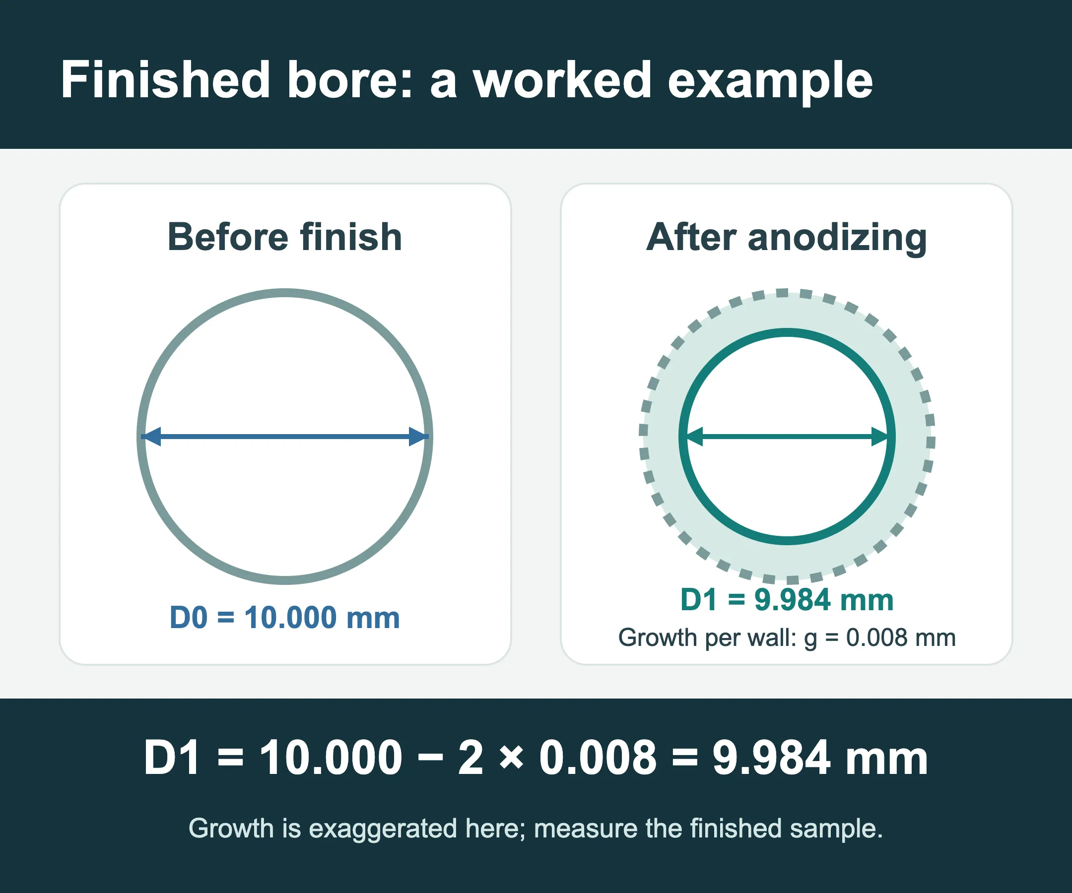
Separate total oxide thickness from outward growth. Anodizing consumes some aluminum while the oxide grows outward; its total thickness is not the dimensional addition per face. Illustrative calculation: a bore is 10.000 mm before processing. Assume 0.008 mm of inward growth on each bore wall for the selected alloy and process. Ignoring preparatory etching, coverage variation and measurement error, the theoretical finished diameter is 10.000 − 2 × 0.008 = 9.984 mm. The 0.008 mm value is an example input; determine the actual allowance from the selected process and representative sample measurements. [1][2]
Powder, liquid and e-coat films add material. If both sides of a bore receive the coating, its diameter is reduced by the actual thickness on both walls. Recesses, corners and edges may not receive the same deposit as a flat panel, so a nominal panel thickness cannot stand in for every part feature. State the finished functional size of bores, threads, sliding faces and seals first; then evaluate masking, machining allowance or process sequence. [2][4][6]
On your drawing, state the coating specification, required thickness and where it will be measured. Where hardness matters, include the applicable test method and measurement location. Confirm dimensional growth for the selected alloy and process, then check representative parts at the functional features. [1][2][3][4]
Compare the complete cost of an accepted part
For a useful cost comparison, keep material, appearance, exposure, critical dimensions, expected batch size and acceptance requirements consistent. Include preparation, coating or conversion, masking, racking, color change, cure, inspection, packaging and any rework. Compare the cost per accepted part that meets your requirements. Minimum batch charges, complex masking and cosmetic rejection rates can change which route costs less. Send us your expected order quantity and critical finish requirements so these factors can be considered together.
For architectural extrusions, compare specified coating systems at the same exposure grade. If your project requires a standard or warranty, confirm its product scope, visible faces, environment and maintenance conditions. Assess service-life requirements separately from laboratory or outdoor test-exposure periods. [6][7][8]
How would the first choice differ for four parts?
- Visible indoor aluminum panel or extrusion: If the metal texture should show, make anodized samples from the intended alloy and preparation. Record color range, rack locations and visible faces. If a uniform opaque color is wanted, compare suitable powder, liquid or e-coat systems with the required aluminum preparation. [1][2][4][6]
- Aluminum enclosure with a ground screw: Draw the current path and actual contact face before choosing the cosmetic finish. Decide whether the contact should be masked or receive a specified conversion treatment. Measure the contact under final fastening conditions. [2][3]
- Aluminum bracket with a precision sliding bore: Give the finished bore size, mating part, motion and wear requirement. Then assess hard anodizing, bore masking or a changed operation order. Check coating coverage and finished fit along with wear performance. [1][2]
- Sun-exposed architectural extrusion: Define the intended appearance, cleaning and maintenance, acceptable change in color and gloss, and the coating performance specification. Then compare suitable architectural powders with PVDF and other fluoropolymer systems for the actual exposure. [7][8]
For all four, match the evaluation to the real exposure. Salt-spray testing under ASTM B117 can provide relative information when specimen and assessment conditions are agreed. Specify the sample preparation, test duration and failure criteria, and assess the result alongside the expected environment. Salt-spray hours alone generally do not convert to years of natural service. [5]
Send HARVLAND your drawing and the part's intended use
Send us a drawing, sketch or photo with the part's intended use and expected quantity. Mark visible faces, close-fitting features, electrical contacts and wear areas where you can. If you have a finish specification or sample, include it; if the alloy, color or treatment is still undecided, mark it “to confirm.” We can use these details to discuss finish options, pretreatment, masking, finished dimensions and sample checks with you.
- [1] Aluminum Anodizers Council, Anodized Aluminum FAQ
- [2] NASA/JSC PRC-5006 Rev. D, Process Specification for the Anodizing of Aluminum Alloys
- [3] NASA/JSC PRC-5005 Rev. D, Process Specification for the Chemical Conversion Coating of Aluminum Alloys
- [4] TIGER Coatings, What Is Powder Coating?
- [5] ASTM B117-26, Standard Practice for Operating Salt Spray (Fog) Apparatus, public abstract
- [6] PPG, E-Coat Process Specifics
- [7] Sherwin-Williams, The Complete Guide to PVDF Coatings for Metal Architecture
- [8] TIGER Coatings, AAMA Powder Coating Requirements in Architectural Design
- [9] Aluminum Extruders Council, Anodizing