A strip shows the forming stages; the finished part needs its own requirements
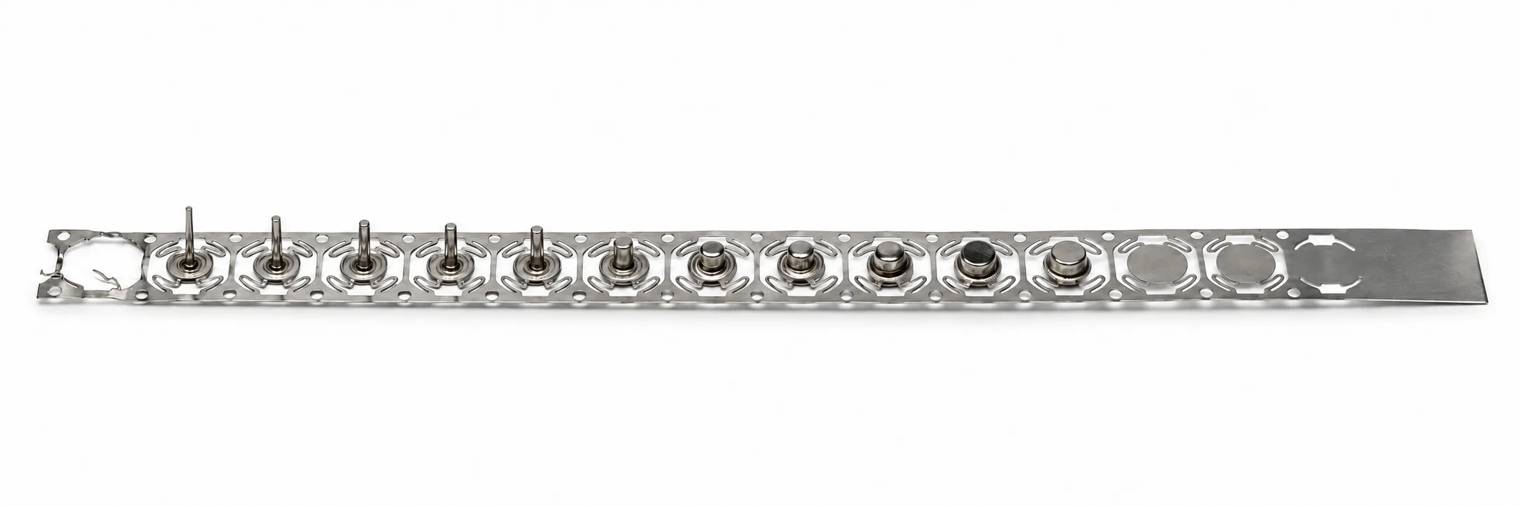
In the strip illustration, the drawn features become progressively narrower and taller from right to left while remaining connected to the carrier. Drawing can require several stages because the change achievable in a single operation is limited. This makes the strip useful for discussing the forming route.
For procurement, also define the part after separation: the retained flange, trimmed edge, opening and overall length may differ from an intermediate stage. The delivery requirement should be a finished-part drawing or an agreed sample specification, with the strip used as supporting process context.
Specify which diameter controls the fit
An outside diameter that enters a mating hole and an inside diameter that receives a pin control different interfaces. Mark the actual contact region and required insertion depth. If both surfaces are functional, show both mating parts and identify the dimensions that must be controlled together.
A diameter measured only at the mouth does not describe the entire length. For a long mating surface, agree the inspection sections and whether straightness, roundness or taper affects assembly. State whether the dimensions apply to the finished surface after plating or coating. Avoid tightening every diameter when only one region locates the assembly.
| What the part must do | Information to provide | What to agree for samples |
|---|---|---|
| Fit into a housing bore | Mating bore, insertion depth and locating region | Finished outside diameter and fit over the required length |
| Receive an internal pin or component | Mating component size, clearance or retention requirement | Inside diameter at agreed sections and insertion test |
| Seat against a flange or shoulder | Contact face and orientation in the assembly | Seat location, relevant form requirements and assembly check |
Separate overall length, useful length and internal depth
Overall length includes features that may not contribute to the working fit. A flange, shoulder, bottom radius or lead-in can reduce the straight length available for insertion. Identify the start and end of the usable region on a section view, and show the face from which length is measured.
For a closed-end part, outside length and usable internal depth are different requirements. Bottom thickness and internal radii occupy space. Describe whether an internal component must stop against the bottom or remain clear of it. Agree the final trimmed length and edge condition after any operations that change the end.
Confirm wall thickness at the locations that matter
Starting sheet thickness is a material input; local wall thickness is a finished-part requirement. Do not treat the stock thickness as proof that the cylindrical wall, bottom and transition regions all have the same thickness after forming. Mark the regions where thickness affects strength, clearance, heat transfer or another specified function.
For an ideal concentric circular section, wall thickness t = (outside diameter − inside diameter) / 2. An illustrative section with a 4.00 mm outside diameter and a 3.40 mm inside diameter gives t = 0.30 mm. This geometric calculation does not establish minimum local thickness or wall uniformity in a real part. Agree measurement positions and a suitable method; a sectioned sample may be needed where direct measurement is impractical.
Define the end, flange and edge details
An open sleeve, a closed-end shell and a part with a pierced bottom need different end requirements. Show which end remains closed, where openings are needed and whether a flange or step locates the part. Put the opening size and position on the finished-part specification rather than assuming they follow from the carrier strip.
Identify edges that pass over seals, touch cables or guide another component. State the required behavior, such as smooth insertion without damage, then agree the edge treatment and acceptance method. If sealing, pressure or electrical contact matters, define the test conditions separately; a closed end or bright metal surface alone does not establish that performance.
Choose material and finish around the application
Provide the material grade, condition and permitted substitutions when known. If they are undecided, describe corrosion exposure, temperature, electrical contact, joining and appearance requirements. Material choice must also be reviewed with the proposed forming sequence; a similar-looking sample is not enough to choose the grade.
Tell us which surfaces need a finish and which must remain available for bonding, welding, electrical contact or a close fit. Agree whether inside surfaces and the closed-end region require coverage, and how the final condition will be checked. Include expected order quantities, likely repeat demand and packaging requirements that protect slender parts from bending or scratching.
Agree sample measurements and assembly checks before production
Use the same drawing revision and the agreed final finish for the sample review. Check the specified diameters, lengths, local thickness and end details, then try the part in the mating assembly. A dimensional report and an assembly check answer different questions and may both be required.
For a thin part that can deform under clamping, agree how it will be supported during measurement and whether the relevant requirement applies in a free or restrained condition. Record open issues and approved changes before releasing production. Keep a reference sample where useful, together with measurable requirements rather than relying on appearance alone.
- Drawing or sketch with the mating and locating regions marked.
- Material and finish requirements, including any undecided items.
- Expected quantity and the required delivery form: separate pieces or an agreed connected format.
- Sample measurements, assembly checks and any separately specified functional tests.