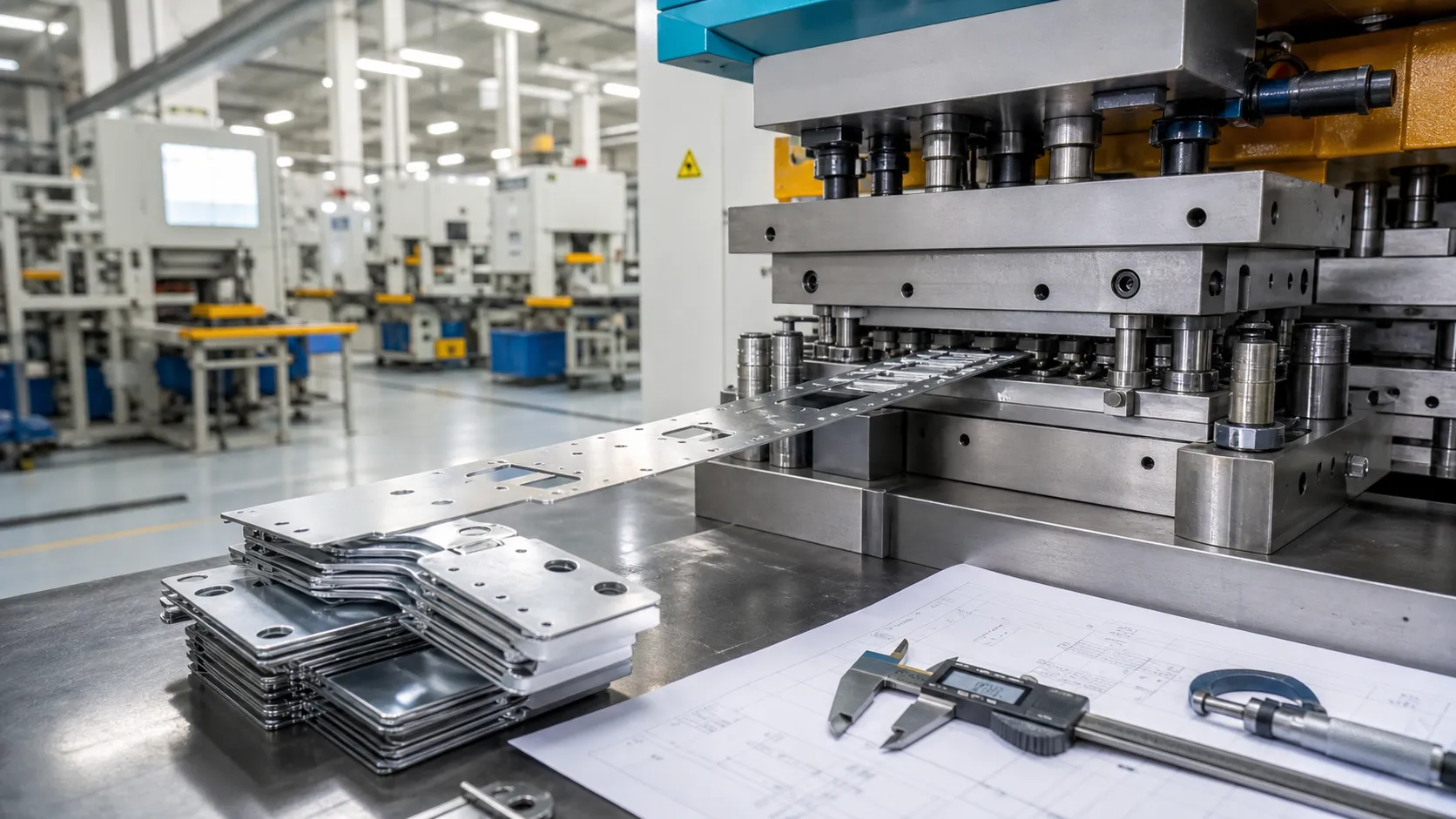
Progressive die stamping can combine piercing, forming, restriking and cut-off operations while a metal strip advances through multiple stations. The result depends on decisions made before the die is built: part orientation, carrier design, feature sequence and strip location.
For an OEM buyer, the practical question is whether the drawing, expected volume and approval plan support a stable production route. This guide explains the inputs that shape that route and the records to request from quotation through recurring production.
Start with the part requirements the die must protect
Plan progressive tooling from the part's function rather than an isolated 2D profile. Identify mating interfaces, datums, critical holes, contact areas, formed heights, burr direction, cosmetic faces and surfaces that must remain free of tool marks. These requirements show which features need support and where later forming could disturb earlier work.
Separate functional requirements from default title-block tolerances. Tight tolerances everywhere can add die detail, restrike operations and inspection effort. Mark dimensions that control fit or assembly and provide mating-part context when it affects design. Resolve open questions during DFM review, before strip layout becomes the basis of the tool.
Design features with strip support and tool access in mind
A progressive die must hold the strip while punches and forming sections enter, work and withdraw. Holes close to an edge, narrow webs, deep forms, short flanges and closely spaced features may leave too little material to support the part during intermediate stations. The concern is not merely whether a single feature is possible; it is whether the partly formed strip can survive every following station without twisting, stretching or losing location.
Review hole-to-edge relationships, bend relief, inside radii, tabs, embosses, lances and cut-outs as one system. Record any feature that can move without changing function; a small change may preserve the carrier or avoid a station. State burr-side and grain-direction restrictions because strip orientation affects both edge direction and material behavior.
Build the strip layout around pitch, carrier and pilots
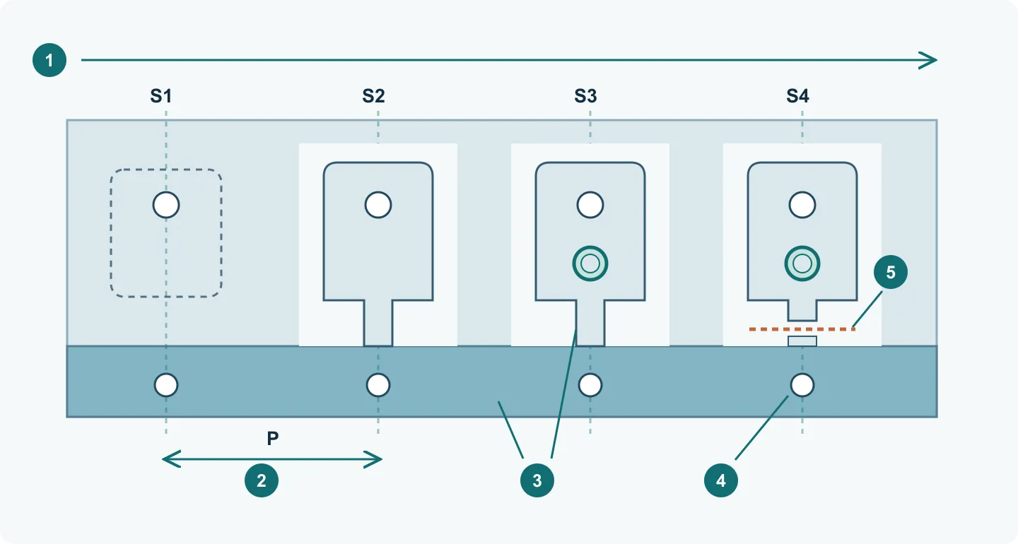
The strip layout shows how coil stock becomes the finished part at each press stroke. It establishes part orientation, feed direction, pitch, stock width, carrier location, scrap bridges and the sequence of intermediate shapes. Material utilization matters, but the layout with the lowest theoretical scrap is not automatically the most reliable. The strip still needs enough stiffness to feed, locate and support the work through every forming operation.
Pitch P is the nominal advance between strokes, not the length of the die or necessarily the length of the finished part. The feeder advances the strip; pilots then correct the remaining position error through prepared holes. Material guides, feeder release and pilot entry must work together. Pilots cannot straighten a damaged carrier or compensate for unrestricted feed error.
- Follow one part through S1–S4: pilot and feature piercing → outline cutting while retaining an attachment → embossing → final cut-off. Other parts occupy the other stations during the same stroke; this is a teaching sequence, not a prescribed die design.
- Find the continuous carrier and the attachment holding the part to it. Check that neither is removed before the final operation that needs support.
- Check the pilot-hole edge and surrounding strip after forming or embossing. Distorted holes, stretched attachments or scrap trapped in the die can defeat otherwise correct station spacing.
Calculate material use per pitch, then check what the number leaves out
Calculation example: a single-row layout makes one part per pitch. Let strip width W = 40 mm, pitch P = 30 mm and net developed part area A = 720 mm² after subtracting holes. The stock area consumed per pitch is W × P = 1,200 mm², so theoretical utilization is A / (W × P) = 60%. The remaining 40% is layout scrap, including the carrier and pierced openings.
For n parts per pitch, use n × A / (W × P) with non-overlapping parts. This geometric ratio excludes coil ends, startup pieces and rejected parts. A narrower carrier may raise the calculated percentage while making feeding unreliable; compare strip stability, accepted output and scrap handling together before choosing a layout.
Sequence stations to manage load and part movement
Each station should perform work without compromising what later stations need. A typical sequence may create pilot holes, pierce internal features, make initial forms, complete additional bends or draws, restrike selected geometry and finally separate the part. The correct sequence depends on geometry and material behavior; it should not be copied from a generic process chart.
Toolmakers distribute work to maintain strip strength, provide punch access and avoid concentrated load. Because forming can shift nearby features, some holes are pierced after major movement while others are created early for location. Lightly loaded stations may support strip recovery, sensing or future correction. Review which operations establish critical dimensions and how they will be checked after forming.
Match material, press and feed assumptions
Material grade, temper, thickness and coil condition influence blanking force, springback, forming limits, lubrication and die wear. Give the supplier the permitted material specification and substitution rules rather than a generic family name. If conductivity, appearance, hardness, plating compatibility or corrosion behavior is functional, include that requirement with the drawing and purchase specification.
The route also depends on press tonnage, bed area, shut height, stroke rate, feed equipment and coil handling. Buyers should request confirmation that the proposed die and press are compatible. State downstream washing, deburring, plating or heat treatment because handling may need to protect surfaces and geometry.
Use realistic volume assumptions for the tooling decision
A progressive die is a production asset, so the quote needs more than the quantity on the first purchase order. Provide expected annual usage, typical release quantity, peak demand, program duration and any forecast uncertainty. These inputs help the supplier select die construction, wear components, automation level, inspection frequency and maintenance planning that fit the program rather than overbuilding or underbuilding the tool.
Compare quotations on total program assumptions. Clarify tooling scope, spare or perishable components, die ownership, storage and maintenance records. Part price should state its volume and material basis. If demand may change, request several annual-volume bands to expose the effects of material purchasing, setups and production rate.
Plan die build and trials as controlled learning cycles
Tool completion is not the same as production approval. Early trials verify strip feeding, pilot entry, station timing, part release, forming behavior and the condition of the finished part. The supplier may adjust clearances, forms, shims, pressure, lubrication or feed settings as trial evidence develops. Buyers should agree on the sample quantity and measurement scope for each meaningful trial stage.
Use numbered trials and drawing revisions so observations remain traceable. A trial report should identify the tool, material, relevant press conditions, measurements, defects, corrections and open-item status. Release production only after the agreed samples, dimensional report, material evidence and finish or assembly checks meet the approval plan.
Define production controls and tool maintenance before launch
A capable trial part does not by itself prove a stable recurring process. Before launch, identify the characteristics checked at setup, during the run and at final inspection. Sensors may be used for feed, part-out, misfeed or other tool conditions, while dimensional and visual checks confirm the output. The control plan should reflect actual part risks rather than treating every dimension with the same frequency.
Maintenance should cover cleaning, lubrication, sharpening, wear-component replacement and verification after tool work. Ask how production counts and maintenance events are recorded and how a repaired die returns to production. If the buyer owns the tool, define storage, preservation, record access, transfer and retirement before purchase order.
Prepare an RFQ that lets engineering quote the real route
Send controlled 2D and 3D files, material and thickness, critical dimensions, burr and cosmetic requirements, finish, annual volume, release quantity and program life. Include mating information, assembly method, packaging needs, required quality documents and the destination when they affect manufacturing or logistics. Mark assumptions that suppliers may challenge during DFM rather than leaving them hidden.
Request the process route, tooling scope, trial plan, sample deliverables, part-price basis, milestones and exclusions. A useful quote exposes engineering assumptions, gives buyers a common comparison basis and reduces the risk that a low price depends on missing operations, incomplete inspection or unsuitable tooling.
| Decision area | Information to provide or request | Why it matters |
|---|---|---|
| Part function | Datums, critical features, mating context, burr side and cosmetic faces | Protects the requirements that drive strip and station decisions |
| Material | Grade, temper, thickness, coil condition and approved substitutions | Affects forming behavior, force, springback and die wear |
| Strip layout | Feed direction, pitch, stock width, carrier, pilots and cut-off point | Connects material use with feeding and part support |
| Station plan | Piercing, forming, restrike, sensing and separation sequence | Shows how critical geometry is created and protected |
| Demand | Annual usage, release size, peak requirement and program duration | Sets the basis for tool construction and part pricing |
| Trials | Trial stages, sample quantities, dimensional reports and approval owner | Creates a controlled path from tool build to release |
| Production control | Setup checks, in-process checks, sensors and maintenance records | Supports repeatability after the approved trial |
| Commercial scope | Tool ownership, spares, storage, maintenance, exclusions and milestones | Prevents quotations from being compared on different assumptions |