From mixing, atomization and leveling to flash-off, curing and actual-part acceptance.
Identify the material and how it forms a film
Liquid paint is applied in a liquid state; in Chinese metalworking, “spraying oil” often means liquid spray painting. The coating may be solventborne or waterborne, one-component or mixed from two components, and may require air drying, heating or another curing route. Its liquid application state does not identify the final resin, weather resistance, hardness or film thickness.[1][2]
These names describe different dimensions. Waterborne and solventborne mainly distinguish the carrier; one- and two-component describe whether specified reactive components must be mixed before use; conventional and electrostatic spraying describe application. They are not mutually exclusive process categories.
| Dimension to confirm | What it describes | Implication for process decisions |
|---|---|---|
| Waterborne or solventborne | Liquid carrier and compatible thinning conditions | Evaporation, humidity, ventilation and cleaning requirements differ; waterborne does not mean free of organic components |
| One- or two-component | Whether specified components must be mixed before use | Check two-component ratio, mixing and usable time; a one-component coating may also chemically crosslink |
| Air drying, baking or another curing route | How a service-ready film develops | Touch-dry alone does not establish that the required properties have developed |
| Conventional or electrostatic liquid spraying | How droplets reach the part | Grounding, gun and coating compatibility affect deposition; they do not replace correct film formation |
Start a process sheet with the actual product technical data sheets (TDS) and the specific primer, topcoat, hardener and thinner combination. Confirm whether the ratio is by mass or volume, the permitted application methods, and each layer’s dry-film and recoating requirements. Matching colors do not establish matching conditions.
For application-method selection, see the conventional and electrostatic spray-painting guide. This article focuses on film control and defects after selecting a liquid coating.
Which stages need control on a part?
A final defect can originate upstream, so inspection should extend beyond the spray gun. Link the following records to material batches, rack positions and time to trace an abnormal result to a particular stage.
| Stage | What to control | Useful process records |
|---|---|---|
| Substrate and pretreatment | Remove the oils, oxides and residues actually present; match treatment to the substrate and coating | Substrate condition, cleaning/treatment batches, rinsing and drying, welds and cut edges |
| Mixing and paint supply | Product combination, component measurement, mixing, filtration and usable time | Products, batches, actual ratio and measurement basis, mixing time, paint temperature and permitted thinning |
| Booth and part condition | Temperature, humidity, ventilation, contamination sources and part surfaces | Ambient/surface temperatures, humidity, dew-point checks where needed, compressed-air and filter maintenance |
| Atomization and spray path | Stable pattern and supply, with motion suited to the geometry | Nozzle, pressure measurement location, supply condition, test spray, distance and path; also grounding for electrostatic application |
| Wet film and intercoat application | Local application amount and condition before the next stage | Wet-film sampling positions, passes, intervals, actual flash-off and recoating conditions |
| Drying and curing | Complete evaporation, film formation and reaction as the product requires | Ventilation/drying conditions; actual part-temperature history and load changes for baked systems |
| Inspection, handling and packaging | Film quality and damage introduced afterward | Dry film, appearance and function; checks during cooling, handling, assembly and packaging |
Cleaning, wetting and adhesion are related, but a visibly clean surface can still carry coating-sensitive residues.[4][10] Treat rust-preventive oil, fingerprints and trapped material on enclosure flanges according to the actual contamination. Confirm that water or cleaning liquid has left recesses; a dry large face is not evidence that every recess is dry.
Record induction time where required, usable time of the mixed paint, flash-off/recoat intervals, and cure time before assembly or service separately. Use the product’s definitions. A two-component mixture that still flows is not necessarily within its specified usable time; additional thinning also depends on the product requirements.
Booth ventilation affects evaporation and occupational exposure control. Follow the relevant safety data sheet, equipment requirements and site rules for solventborne or reactive-component systems; the waterborne label does not replace them. Arbitrarily reducing airflow to reduce overspray also changes film-formation conditions.[1][2]
Why atomization, leveling and sag resistance interact
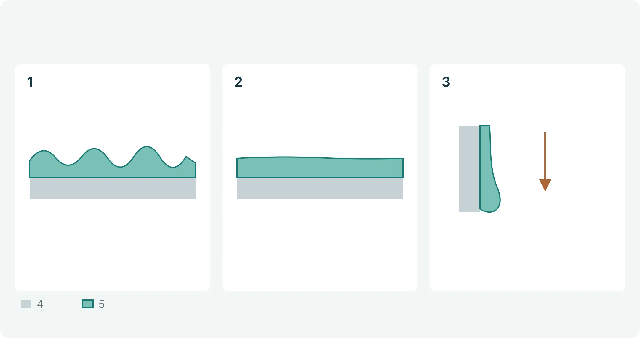
Atomization breaks a liquid into droplets; leveling lets the deposited wet film become smoother. The initial droplet-generated surface unevenness must diminish before the film loses mobility. Evaporation, temperature, resin reaction and rheology change this time-dependent process.[1][2][5]
Lower viscosity may help atomization and leveling but can increase sagging on vertical surfaces. Easier liquid movement also allows gravity-driven flow. Excessive application can cause buildup on upright faces, holes and flanges even with an otherwise suitable paint.[1]
A paint experiences different shear conditions at rest, during mixing, in the gun and after deposition. Shear thinning describes viscosity changing with shear; thixotropy also involves the time taken for structure to recover after shear stops. Similar readings from one routine viscosity test do not establish similar leveling or sag resistance after spraying.[5]
A viscosity cup can monitor changes in the same system under a specified cup, paint temperature and procedure. One efflux-time reading does not describe all spray behavior. If panels look normal but vertical parts sag, investigate wet-film amount, geometry, orientation and post-deposition flow before requesting a rheology change from the coating supplier.[1][5]
Orange peel is not simply thick paint. Initial atomization unevenness, evaporation, surface-tension differences and underlying texture can all contribute.[1][4] Identify the first affected layer, whether a path change alters the pattern, and the environment between spraying and loss of mobility before adjusting the process.
Use wet film to control dry film, with stated assumptions
Wet-film thickness (WFT) provides immediate control of application amount; dry-film thickness (DFT) checks the final requirement after film formation. They are related but not interchangeable. A notch gauge gives an approximate reading and disturbs the wet paint by contact. Measure promptly at suitable locations and record position and method.[7]
A simplified volume relationship is: dry-film thickness ≈ wet-film thickness × as-applied volume-solids fraction. Include permitted thinning in that fraction. Do not substitute mass solids or automatically use unmixed-product data for a mixed and thinned coating.[7]
Calculation example. Assume correctly mixed paint at 50% volume solids and a target 60 μm dry film. Ignoring other volume changes, the estimated unthinned wet film is 60 ÷ 0.50 = 120 μm.
Now assume the 1.000 L mixture permits 0.100 L of compatible zero-solids thinner, with approximately additive volumes. Solid volume remains 0.500 L, so the as-applied volume-solids fraction becomes 0.500 ÷ 1.100 ≈ 45.45%. The estimated wet film for the same 60 μm dry film is 60 ÷ (0.500 ÷ 1.100) = 132 μm.
These numbers explain thinning’s effect; they are not a mixing recipe or thickness recommendation. Check product requirements, volume-solids measurement conditions and actual DFT. Some flat coatings depart from the simple estimate. WFT cannot be used to infer or verify the coating’s solids content.[7]
WFT does not determine actual paint utilization because it excludes overspray, transfer losses and equipment residue.[7] Pass count is also no substitute for thickness records: identical counts can produce different distributions through supply, path and local overlap.
For final DFT, select an instrument for the substrate and measurement object, and check calibration, verification and adjustment. One reading does not represent the whole part. Check suitability at edges, curves, rough or small areas. For multilayer systems, state whether the result is cumulative thickness or an individual layer obtained by an applicable method.[8]
Distinguish flash-off, touch-dry and cure
Flash-off usually allows required evaporation and film development before another layer or subsequent cure. A non-tacky surface is one observation; complete film formation and the specified cure state are separate questions.[2][11]
Waterborne dispersions require more than water evaporation
For polymer particles dispersed in water, idealized film formation involves evaporation, particle packing and deformation, and polymer-chain interdiffusion across particle boundaries. Different locations in a real film can be at different stages simultaneously. Two-component waterborne systems also require chemical reaction.[2]
Temperature, humidity and airflow affect evaporation and particle joining. High humidity may delay water removal; excessive airflow or rapid surface drying can create uneven film formation and make internal evaporation harder. Where minimum film-formation temperature matters, check the actual formulation. One latex temperature is not a rule for every waterborne paint.[2]
Baking does not replace required evaporation
Excessive wet film, insufficient flash-off or early surface barrier formation during heating can impede water or solvent escape and cause holes, popping or other defects.[2][3] Check flash-off, pre-oven wet-film amount and actual heating, rather than only extending final bake time.
A steel-panel study compared atmospheric and catalytic infrared drying of specified two-component waterborne primer/intermediate and polyurethane topcoat systems. It used spiral applicators under controlled material and pretreatment conditions and observed drying-route effects on surface morphology.[3] Cycle time, appearance and protection therefore need separate validation; the study does not establish that any sprayed part can switch directly to rapid infrared drying.
If a product specifies baking by part temperature, check the actual part-temperature history. Thickness, rack position and loading can change heating. For air-curing systems, use their specified environment and time rather than a baking system’s temperature.
An applicable solvent-rub test can help assess solvent resistance of a chemically curing coating, but a resistance level alone does not prove full cure. Solvent, double-rub count and acceptance criteria are not universal values for all coatings.[11]
Organize defects by appearance and first occurrence
The table is an investigation starting point. Every listed cause is a possibility to verify. Record appearance, stage and distribution before checking the associated process; do not record a defect name as an established cause.[1][2][4][6]
| Observation | Useful description | Possible processes | Priority checks and comparisons |
|---|---|---|---|
| Orange peel, poor leveling | Continuous unevenness; present after spraying or more visible after drying? | Initial atomization, rheology, evaporation and surface-tension differences; underlying texture | Compare wet/dry photos, undercoat appearance, WFT and environment; check spray pattern and paint flow behavior |
| Sags, runs | Downward bands or lower-edge buildup; worse on vertical faces? | Local overthickness, mismatch between wet-film flow and recovery, slow evaporation | Compare WFT, overlap and orientation at uprights/flanges; do not rely only on additional thinning |
| Dry spray, rough overspray | Grainy, rough or low-gloss areas; concentrated on adjacent or sheltered faces? | Too much evaporation before landing, overspray redeposition, path or airflow effects | Check distance, supply, atomization, sequence and booth airflow; distinguish hard dirt particles |
| Craters, fisheyes | Round or irregular depressions, possibly thin at the center | Local wetting/surface-tension differences; substrate contamination, other paint mist, particles or internal incompatibility | Compare clean controls and actual parts; trace oil, silicone contamination, neighboring overspray and material changes |
| Pinholes, small holes | Count, rim appearance and the stage of first occurrence | Entrained air, volatile escape or incomplete local film formation; more than one cause | Look for microbubbles in wet film; compare before/after flash-off and heating; inspect sections if needed |
| Solvent or water popping | Broken-bubble pits or holes after drying/heating | Trapped volatiles; thickness, flash-off and heating mismatch | Check local wet film, pre-oven state and actual heating; verify factors separately with controlled specimens |
| Dirt nibs, particles | Raised features rather than only depressions; identifiable solid particles? | Environment, substrate, filtration or paint-supply contamination | Preserve particles and untreated parts; trace sources/distribution; do not label all roughness dry spray |
| Floating, mottling, color differences | Overall shift or local patches; does viewing angle change the appearance? | Pigment distribution, agitation, atomization and wet-film flow; effect-pigment orientation | Fix lighting/viewing angle; compare batch, racking, path and film thickness; first confirm undercolor and hiding |
| Wrinkling, lifting, intercoat defects | Does the previous layer swell, distort or separate after the next layer? | Layer compatibility, underlying condition, recoat window or solvent action | Identify products and times for every layer; compare compatibility and recoat conditions on the same undercoat |
| Softness, renewed tack or abnormal cure | How long does softness persist; do handling/packaging leave imprints? | Insufficient evaporation/film formation, components/reaction conditions, excessive thickness or usable-time deviations | Check mixing, environment, thickness, cure records and test timing; rebaking is not a universal fix |
Mottling in metallic-effect paints may involve platelet orientation, which spraying and wet-film flow can change. The same color number need not produce the same angle-dependent appearance.[1] With solid colors, distinguish inadequate hiding, undercolor differences and an actual color shift before calling every difference floating.
For small holes, separate three investigation directions
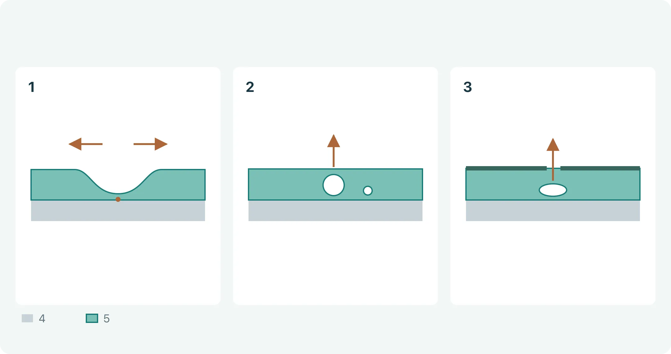
Craters, entrained-air holes and volatile-escape holes can all become depressions. They need different verification. One photograph of the finished part is usually insufficient for a firm attribution.
First: local wetting or surface-tension differences. Local substrate contamination, foreign paint mist or particles landing in a mobile film can move liquid outward and create craters.[4] Clean controls, contamination distribution and neighboring application are more informative than simply raising bake temperature. Silicone is one possible contaminant, not the cause of every crater.
Second: air entrained in the liquid. Mixing and delivery can introduce bubbles. Whether they leave holes depends on escape and recovery after rupture. Surface defoaming and air release within the film play different roles; no large bubbles in the container does not establish no microbubbles in the film.[6]
Third: volatiles escaping during film formation or heating. Determine whether holes already existed in wet film or appeared after flash-off/heating, and whether thicker areas are worse. Waterborne coatings can also suffer impeded escape; this is not restricted to solventborne paint.[2][3]
Select defoamers or anti-cratering additives through formulation compatibility and comparisons. Defoamers use controlled incompatibility; excessive incompatibility can cause craters, haze or gloss changes. Dose, incorporation and actual application affect results, so more is not automatically better.[6] A suitable silicone surface additive is different from uncontrolled external silicone contamination; excess dosage or unsuitable heating may affect recoating.[4]
Narrow causes with controls, then verify actual parts
A useful trial answers a specific question and retains the original condition as a control. Improving appearance after simultaneously changing pressure, thinner, thickness, flash-off and baking identifies a different combination, not which factor caused the improvement.
| Hypothesis | Example comparison | Question answered | Remaining confounders |
|---|---|---|---|
| Craters originate in actual substrate contamination | Same coating batch and application: compare a validated-cleaning control with actual parts | Is the substrate route associated with the defect? | Material, roughness and geometry differences between clean panels and parts |
| Pinholes relate to thick film or flash-off | Within product limits, compare thickness or flash-off separately with other conditions comparable | Does the defect change with that factor? | Air in the paint, supply abnormalities and actual heating differences |
| Sags concentrate at path overlaps | Same paint/environment: compare measured WFT distribution and controlled paths | Relationship between local application amount and sagging | Unstable pattern, orientation and paint-temperature changes |
| Dirt comes from the environment rather than paint | Compare environmental witness samples, supply samples and parts during one application period; identify particles | Is there a traceable particle source? | Exposure time and detection-method differences among samples |
- Preserve the initial condition. Keep defective and normal parts before sanding, cleaning or repair. Record batch, discovery stage and location. Photograph overall distribution and local details.
- Find common conditions in the distribution. Is it one batch, one rack side, after a color change or only a thick flange? Record unaffected parts from the same batch too.
- Compare process records with product requirements. Identify clear mismatches, then form a testable hypothesis. Measure unknowns rather than substituting operator impressions.
- Start with discriminating comparisons. Keep materials, undercoat, geometry and other key conditions comparable; change the factor being tested and record actual values.
- Confirm on multiple independent specimens. Retain repeats and normal controls to avoid treating a chance result as stable improvement. Designed multifactor trials can address complex interactions afterward.
- Verify actual parts and finished requirements. Panels compare coating and process behavior but do not represent deep flanges, threads, thermal mass or assembly contacts.
These are investigation suggestions, not completed trials. Check side effects: less orange peel but more sagging, defoaming but new craters, or shorter cycles with changed adhesion/solvent resistance.[1][3][6][11]
Rework the layer where the defect originates
Sanding, polishing, local repair, recoating or removal depend on depth, film condition and service requirements. Establish whether the original film can remain before choosing a route. A covering topcoat does not automatically restore protection beneath it.
Surface correction may be evaluated for local texture or dirt nibs, but check remaining thickness, gloss and color to avoid cutting through the film or changing effect-pigment appearance. Through-holes, widespread intercoat failure or substrate contamination require deeper investigation, not only surface polishing.
Before respraying, check the old layer, product compatibility, recoat conditions, sanding and cleaning. Additive changes also need subsequent intercoat-adhesion checks; solving craters should not leave a recoat problem for the next stage.[4]
If paint is peeling, identify whether failure is at the substrate interface, between layers or within the film before setting the removal depth. See the paint-peeling and adhesion guide. Retain original batch and rework count, and recheck appearance, thickness, adhesion and assembly. Repeated heating also requires checking substrate/component tolerance.
Write repeatable acceptance checks
Smooth, pinhole-free and well adhered describe goals but omit viewing conditions, sampling locations and test methods. Record appearance, film and functional requirements separately so the supplier and inspectors can repeat the same checks.
| Acceptance object | Conditions to define | Limits of the result |
|---|---|---|
| Appearance defects | Cosmetic-face grades, lighting, distance, angle, time, limit samples and defect size/count criteria | Unspecified photos do not replace agreed acceptance; distinguish micropores from through-holes |
| Color and effect | Approved sample, undercolor, film state, instruments/viewing conditions; angles for effect paints | A color number does not guarantee identical angle-dependent appearance |
| Gloss and texture | Agreed geometry, locations and range; evaluate texture separately with samples or an applicable method | One gloss value cannot fully describe orange peel, reflection haze or distinctness of image[9] |
| Dry-film distribution | Individual-layer/total requirements, instrument suitability, calibration verification and representative positions | A large-face average cannot conceal thick flanges or thin edges[8] |
| Cure and adhesion | Product conditions, test timing, applicable method/version; retest after relevant environmental/mechanical exposure where needed | Tape ratings are not absolute bond strength; a specified solvent-resistance level does not establish full cure[10][11] |
| Assembly and protection | Threads, fits, seals, electrical contacts and application-specific exposure/reinspection | An attractive panel does not prove every location and service condition meets requirements |
ASTM D3359 assesses cut-and-tape adhesion under specified conditions. It does not finely differentiate high adhesion and is not technically equivalent to ISO 2409.[10] Compare methods, thickness, specimen condition and failure location, not rating numbers alone.
Appearance acceptance does not automatically establish corrosion/weather resistance or assembly compliance. Inspect the full substrate–pretreatment–primer–topcoat system and critical coverage, then verify against the intended service. Agree test methods and acceptance separately; do not infer lifetime from the process name.[1][2][3]
Apply the method to enclosures and brackets
For a steel enclosure with flanges, studs and welds, organize sample checks around these locations rather than only the easiest large face:
- Large cosmetic faces: check orange peel, particles, color and gloss, including texture transferred from the undercoat.
- Flanges and vertical faces: check overlapping wet film, lower-edge buildup and sags; behavior can differ from a panel.
- Inside corners and welds: check cleaning, dryness and coverage; investigate local holes and residue.
- Threads and fits: confirm masking, film buildup and assembly requirements; forced assembly does not establish intact coating and function.
- Grounding and electrical contacts: define no-coat areas or the contact design first, then check the assembled electrical path.
- Hanging and handling points: define allowed marks and repairs; distinguish application defects from later damage.
Turn these locations into a drawing inspection map and relate it to each layer’s records. An e-coat primer with a liquid topcoat needs compatibility, recoating and heat-treatment checks; two separately acceptable coatings do not automatically make an acceptable combination.[1][4] See the electrocoating guide for deposition and cavity access.
Start with drawings, sketches or photos, purpose, expected quantity, cosmetic faces, fits and conductive locations. For defects, add discovery stage, batch and unrepaired photos. Mark unresolved coating, thickness or inspection requirements “to be confirmed” to select meaningful samples and quotation conditions.
- [1] Evolution of the Automotive Body Coating Process—A Review
- [2] From Wet to Protective: Film Formation in Waterborne Coatings
- [3] Durability and Corrosion Properties of Waterborne Coating Systems on Mild Steel Dried under Atmospheric Conditions and by Infrared Radiation
- [4] BYK Surface Additives
- [5] BYK Rheology Additives
- [6] BYK Defoamers and Air Release Agents
- [7] ASTM D4414-25
- [8] ASTM D7091-22
- [9] ASTM D523-25
- [10] ASTM D3359-23
- [11] ASTM D5402-19(2024)