1. Define which part of the material you need to measure
“Measure this sheet’s hardness” is not specific enough. Is purchasing checking the substrate in its supplied condition, is engineering examining a locally worked area after bending, or is the objective to characterize a coating? Sampling locations, preparation and suitable methods can differ. One result cannot serve all three purposes.
| Measurement target | Link the specimen and location | Results that cannot directly replace it |
|---|---|---|
| Incoming substrate and supplied condition | Identify coil/lot, surface or cross-section, thickness and sampling location | Finished-part hardness from an unknown location; readings through an unspecified surface layer |
| Bending, shearing or another locally worked area | Record distance and direction from the worked feature and the condition before or after processing | A single reading on a distant flat area |
| Coating or modified surface layer | Identify layer type and thickness, and whether testing is on the surface or cross-section | Substrate hardness; composite readings significantly influenced by the substrate |
For example, if a material certificate has a hardness field but no value, first check whether the order requires the test and whether a separate report exists. A blank field means neither zero nor automatic acceptance. If an SDS or environmental test document does not provide the lot’s hardness and test conditions, the grade name cannot supply a missing value.
For a thin coating, reducing the Vickers test force does not guarantee that only the coating is measured. Check the method’s scope for indentation readability, layer thickness and measurement direction. Where necessary, the laboratory should select an appropriate cross-sectional or instrumented indentation method. The scope of ISO 6507-1:2023 distinguishes conditions for coating measurements on surfaces and cross-sections.
2. HV and HRB are more than different suffixes
Vickers hardness, HV, uses a diamond pyramid to make an indentation and then measures both diagonals. Rockwell hardness uses the difference in penetration depth during a specified loading and unloading sequence. The readings have different bases: for example, 200 HV and 80 HRBW cannot be ranked by numerical magnitude or treated as the same quantity after removing the scale. Vickers method and diagonal measurements; NIST Rockwell hardness guide, Chapter 2
Keep the test-force designation after HV. HV 0.5 corresponds to 0.5 kgf, approximately 4.903 N, not 0.5 N. Record the actual force and dwell time as well. If the dwell time is outside the method’s usual specified range, include it in the result designation as required. Do not infer conditions solely from an abbreviated software display. Mitutoyo Vickers test-force table
HRB is a common designation for the Rockwell B scale. Results obtained with a tungsten-carbide ball may be designated HRBW, where W identifies the indenter material. For an HRB requirement on an older drawing, check the method edition, ball indenter and full report designation. Do not assume that different indenter conditions have been established as equivalent. Mitutoyo Rockwell scales and ball-indenter designations
Distinguish regular Rockwell from superficial Rockwell. Superficial Rockwell has its own force combinations and scales, such as HR15T and HR30T. The word “superficial” does not mean that the result represents only a coating. Method selection also depends on specimen and target-layer thickness, material hardness range and the order requirements. Scope of ISO 6508-1:2023
3. A thin specimen’s back face and support can affect the reading
Material around the indentation also deforms under load. If the specimen is too thin relative to the selected indentation, the back face or underlying support can influence the reading. Rocking, bending or trapped debris also changes the conditions. Unusual marks on the back face are useful clues during review, but the absence of a visible mark alone does not establish test validity.
Check the applicable standard’s thickness requirements together with material and hardness range, indenter and force. Do not assign one minimum thickness in millimeters to every steel sheet, copper alloy or coating. Buehler’s technical guidance also considers thickness, scale and support together. Thickness and support in Rockwell testing
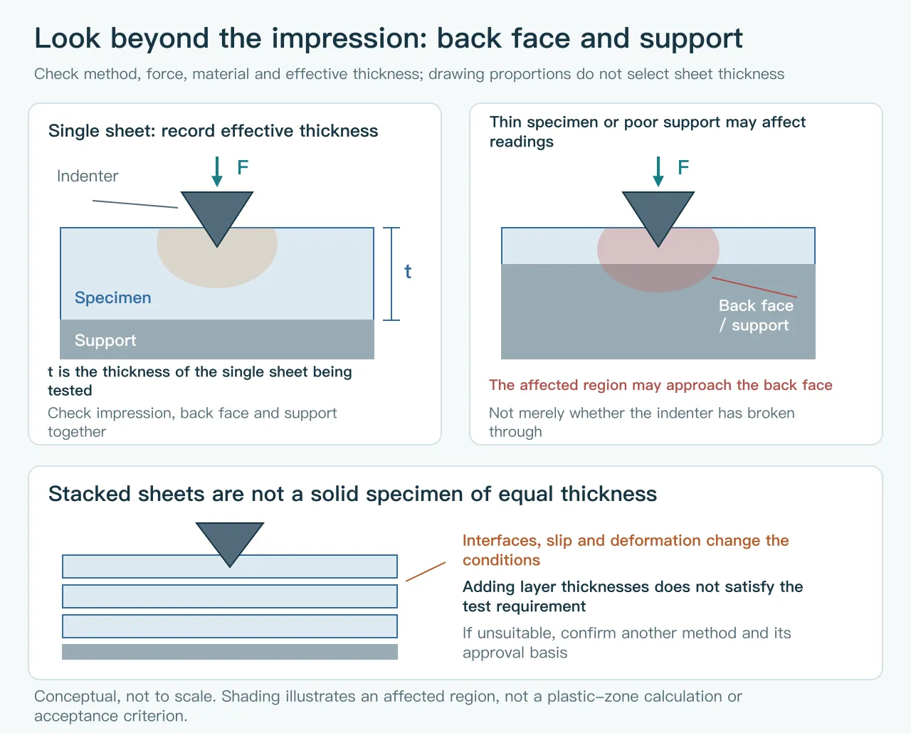
Stacking thin sheets does not turn the top sheet into a solid specimen of the combined thickness. Gaps, slip and deformation between layers introduce additional effects. Stacking cannot make up the material thickness required by a regular test. If the available scale is unsuitable, agree on an alternative method under the order and applicable standard, and retain the approval basis. Instron FAQ on thin specimens and stacking
A lower force is not always better. Very small Vickers impressions are harder to read reliably, and surface condition and measurement error have a greater influence. Within the method’s permitted range, balance thickness, the target region and indentation readability. Do not keep changing force to find an easier passing number.
4. Preparation and test locations must follow the inspection objective
Record the original coil or lot, sheet identity, face, actual thickness and sampling location before cutting specimens. Control heat effects and work hardening during cutting, grinding and polishing. A result must not be labeled “original sheet hardness” after preparation has changed the condition being measured. Repeated hammering or flattening to seat an uneven specimen can also alter the local condition.
For incoming substrate testing, explain how oil, oxides or coatings are handled and whether their removal affects the target region. For surface-layer testing, preparation must instead preserve the layer and its interface. Mounted specimens also require appropriate methods, clamping and support; preparation suitable for microscopic cross-section examination cannot automatically be transferred to every Rockwell test.
Maintain the method’s required distances between impressions and from edges; requirements can also vary with material type. Do not apply steel spacing rules unconditionally to a soft coating, or measure next to a sheared edge and call the result substrate hardness. If the purpose is to examine a shear-hardened region, retain that location and describe it with a dedicated test-point plan. Vickers preparation and indentation spacing
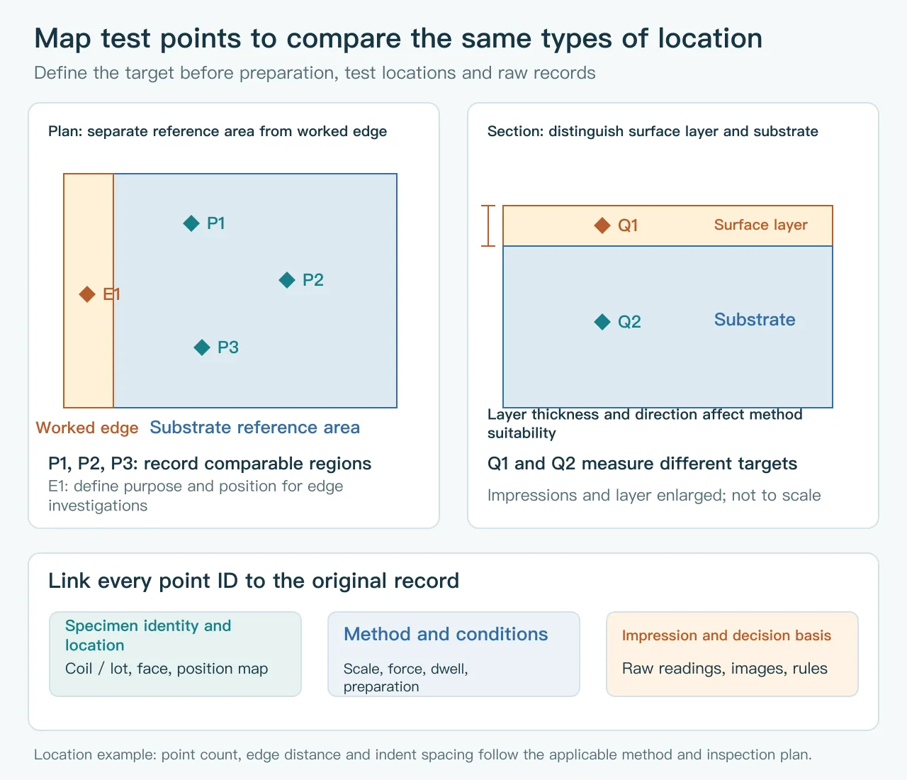
The map should allow another inspector to find the same type of location, rather than merely stating “three random points.” The inspection plan defines distribution, number of points and the represented inspection lot. Adding impressions within one small area does not automatically make it more representative of an entire coil.
5. Trace a Vickers result back to its original impression
The following hypothetical calculation record illustrates how the data relate. Assume three separate impressions on one teaching specimen, all at 0.5 kgf with a dwell time of 15 s. Assume that preparation, thickness and test-point validity have already been confirmed under the applicable method. No material grade, sheet thickness or acceptance interval is specified here.
Calculate the mean diagonal as d=(d1+d2)/2. With F in gf and d in μm, HV=1854.4F/d²; here F=500 gf. Vickers formula and units
| Impression | d1 (μm) | d2 (μm) | Mean d (μm) | Calculated HV, approximate |
|---|---|---|---|---|
| P1 | 67.0 | 69.0 | 68.0 | 200.5 |
| P2 | 68.0 | 70.0 | 69.0 | 194.7 |
| P3 | 66.0 | 68.0 | 67.0 | 206.5 |
For P1, 1854.4×500÷68.0²=200.5. If this teaching record is displayed as a whole number, it may be shown as approximately 201 HV 0.5, while retaining both diagonals, dwell time and location in the original record. The digits, rounding and reporting of a real result must follow the adopted method, rather than copying this example’s display format.
The table illustrates calculation and recording, with no acceptance limits. These three numbers therefore cannot establish that the entire lot passes. Also check that the impression outline is readable, both diagonals meet the method’s requirements, and the locations represent the intended scope. Impression images help review, but do not replace equipment-status and test-condition records.
6. Establish comparable conditions before discussing conversion
If one report for a lot uses HV 0.5 and another uses HRBW, first establish which method the order requires. Conversion tables express approximate relationships for particular materials and conditions. They cannot make an unsuitable thin-sheet test valid, and a converted value must not be presented as a direct measurement. NIST guide, Section 3.4.11
Even when both reports say HV, force, preparation or location differences prevent comparison of the final numbers alone. Distinguish original from processed sheet, surface from cross-section, and substrate from surface layer, and inspect the original records. An instrument’s ability to display a converted result does not establish that the conversion is accepted for the order.
If another scale is needed for process control, establish a comparison basis for that material and condition in advance, with a clear purpose and approval procedure. Purchasing acceptance still follows the agreed metric. Where conditions are unclear, record “insufficient comparable evidence; review required,” rather than immediately declaring the material too soft or too hard.
7. Complete the report, then apply the agreed decision rule
A hardness report should link results to specimens and specimens to the incoming lot. The fields below provide a review framework for the inspection plan and report. The actual test procedure still follows the adopted standard and laboratory method.
| Record item | Information to retain | Misinterpretation it helps prevent |
|---|---|---|
| Material and specimen identity | Grade, standard, condition, coil/lot, specimen ID and thickness | Mixing different conditions or lots |
| Method and equipment | Method standard and edition, scale, indenter, equipment ID and relevant verification records | Seeing “hardness passed” without knowing how it was tested |
| Test conditions | Force, loading and dwell conditions, support, preparation and environmental records | Mistaking back-face, support or preparation effects for material differences |
| Locations and raw data | Face, plan/cross-section location, impression ID; both Vickers diagonals and available images | Losing abnormal locations or retaining only the mean |
| Decision basis | Order limits, individual or statistical requirements, rounding and agreed uncertainty treatment | Choosing a favorable rule after seeing the results |
| Review and disposition | Original abnormal records, retest reason, affected scope, approval and material destination | Retesting different points until a pass appears or overwriting original results |
If results exceed a limit or approach a boundary, retain the originals, check location and method suitability, then arrange retesting as agreed. Explain and retain evidence for impressions confirmed invalid; do not delete a result merely because it is lower. If every point must comply, a passing mean cannot conceal an individual failure.
After hardness acceptance, verify forming, assembly and spring function against their own requirements; see spring material condition and force retention for these distinctions. For purchasing, provide the existing hardness requirement, material thickness, surface condition and available reports. If the method is still undecided, explain whether the aim is incoming condition control or local finished-part performance, then discuss practical inspection conditions.
- ISO 6507-1:2023: Vickers hardness method and scope. Method scope
- ISO 6508-1:2023: scope of regular and superficial Rockwell methods. Method scope
- ZwickRoell: Vickers measurement, force and dwell time
- Mitutoyo: HM-200 Vickers test-force table
- Mitutoyo: Rockwell scales and ball-indenter result designations
- Buehler: thickness, support and conditions in Rockwell testing
- Instron: hardness testing FAQ
- Struers: Vickers calculation, preparation and indentation spacing
- NIST SP 960-5: Rockwell hardness measurement guide. Used for measurement principles and conversion limitations; acceptance follows the current method specified by the order