1. Turn “1.0 mm” into a requirement that can be evaluated
The inspection record should identify the material grade, product form, specification and edition, thickness requirement, sheet width and applicable tolerance class. Hot-rolled sheet, cold-rolled sheet, metallic-coated material and strip slit from a wider coil do not automatically use the same tolerance table just because their nominal thickness matches.
Distinguish ordering to a nominal thickness from ordering to a minimum thickness. The former needs the relevant positive and negative deviations. For a minimum-thickness order, read the scope and permitted positive deviation as well; do not rewrite it as a symmetric plus/minus tolerance. U. S. Steel’s coated-sheet supply information, for example, provides separate tables for the two conventions, with thickness and width bands.[1]
If the drawing, purchase order and supplier confirmation conflict, clarify the governing controlled requirement. Do not select a more generous table after seeing a low reading. A gauge-conversion value does not by itself define the acceptable range for received material.
2. Choose the instrument by the task, not by its decimal places
The instrument must reach the required location and suit the surface and thickness range. A conventional outside micrometer has limited throat depth. Where the inspection requires interior points on a wide sheet, arrange an accessible method or approved sampling and preparation. Readings from the reachable edge alone do not establish the thickness of the whole sheet.
Display resolution concerns the change in indication that can be distinguished; it is different from measurement accuracy. Selection also requires the applicable maximum permissible error, calibration or verification status, repeatability and measurement-process uncertainty. A display reading to 0.001 mm is not a guarantee that the result is accurate to that amount.[2][3]
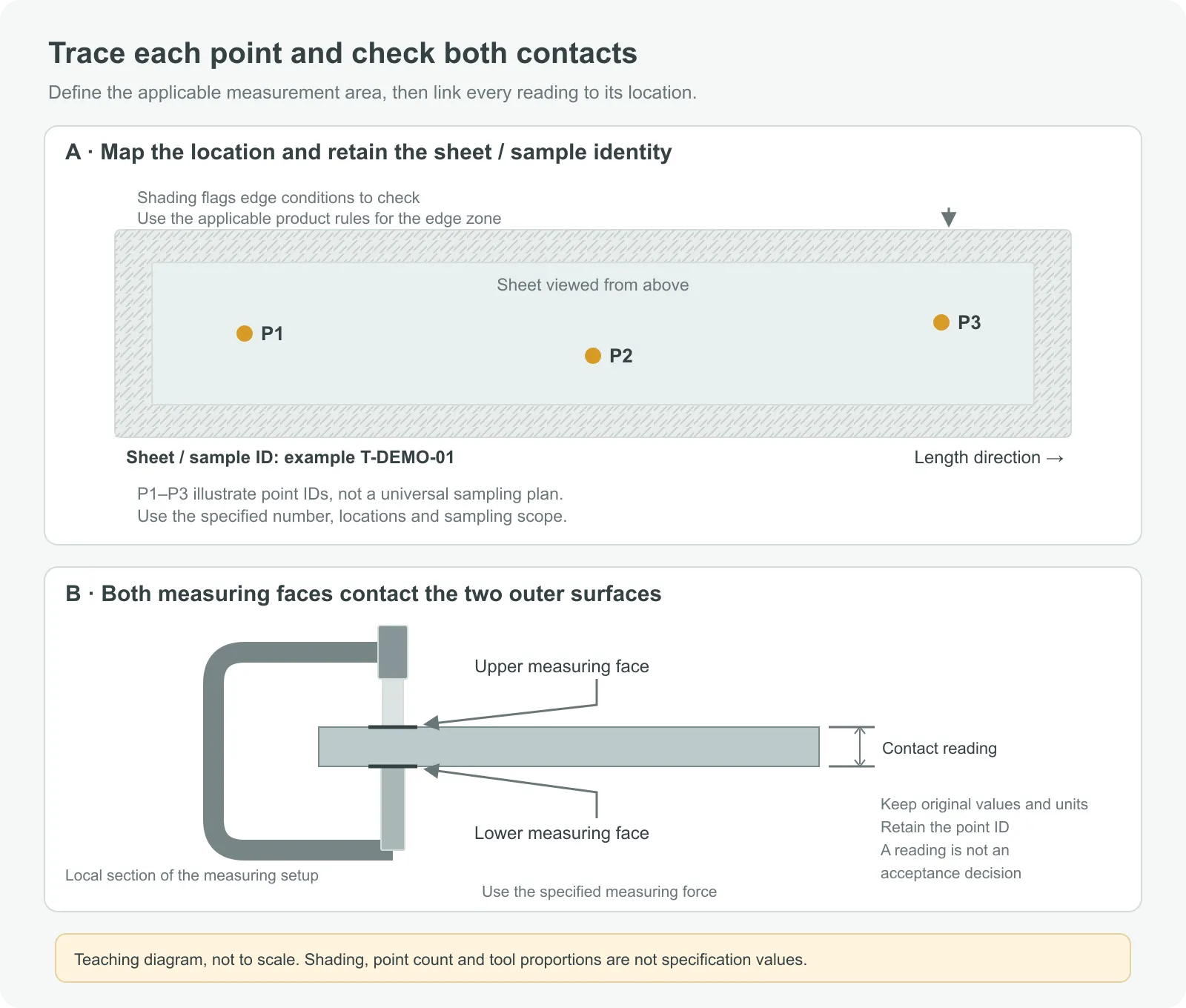
Before use, clean the measuring faces, check smooth movement and verify the zero or an appropriate reference as the instructions require. A zero check does not replace calibration across the measurement range. Allow the instrument and material to reach stable, similar temperatures in an appropriate environment. Use the specified constant-force device instead of tightening the thimble harder by hand. Mitutoyo’s outside-micrometer guidance explicitly addresses temperature, cleanliness and measuring force.[4][5]
3. Make every point traceable to the sheet
Identify the sampled sheet or specimen and retain its connection to the coil, plate or receiving lot. Record the locations of the points. Distributing points across length and width can help distinguish location-related readings, but their number, positions and selection still come from the applicable product requirements and inspection plan.
A sheared burr, turned edge or local deformation can change the contact condition. Product requirements may also exclude a defined edge region and distinguish mill edges, cut edges or narrow strip. U. S. Steel’s supply guidance includes an edge-distance condition for its corresponding coated-sheet products.[1] Check the rule for the actual product; one edge distance is not a universal rule for all steel sheet.
Separate acceptance points from extra points added to investigate an edge anomaly. Do not silently grind a shiny depression into the surface and describe the resulting thickness as the original condition. If preparation is needed, define the method and whether it changes the substrate or coating.
4. With coated sheet, identify the two surfaces being measured
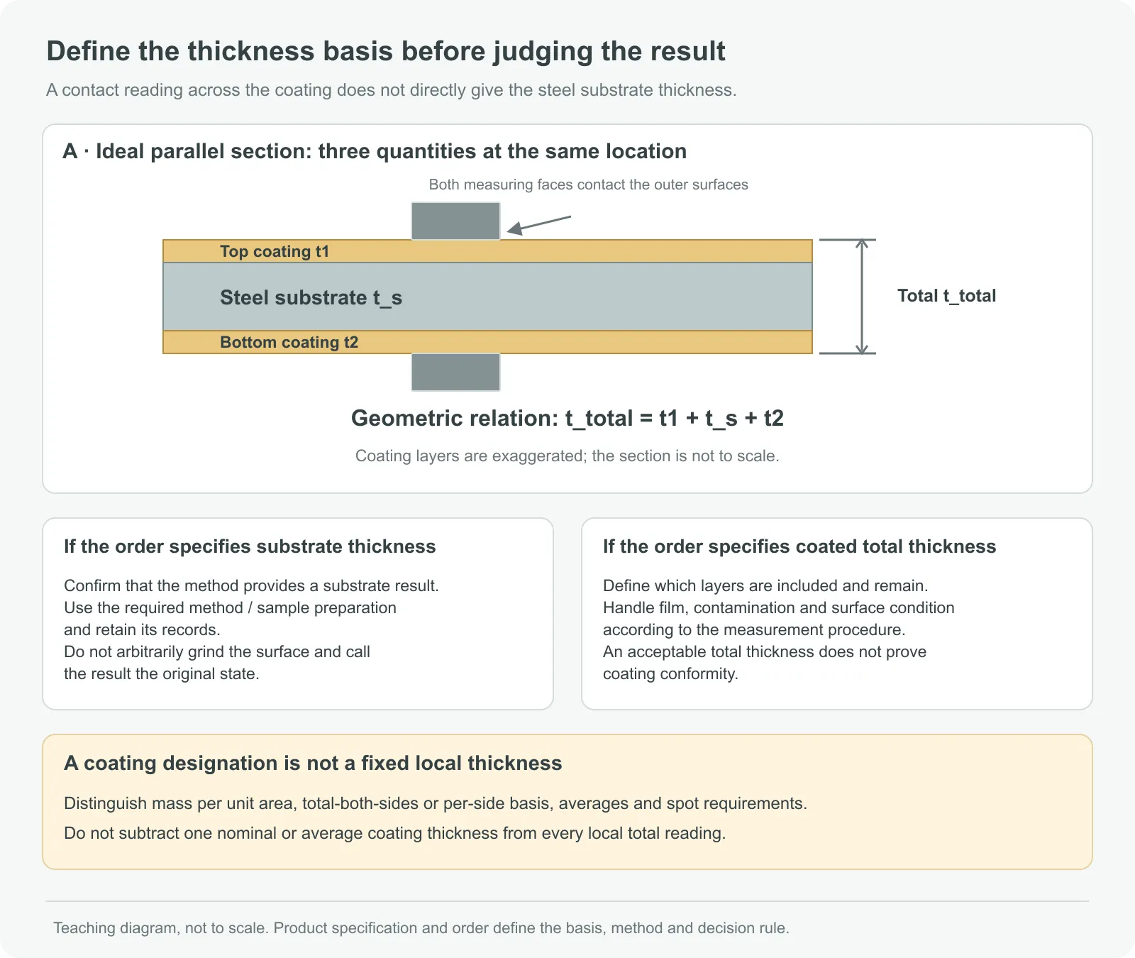
An ordinary contact outside micrometer applied to coated sheet reads the distance between the two outer contact surfaces. In an ideal parallel three-layer section, total thickness equals steel substrate thickness plus the two coating thicknesses. This geometric relationship does not mean those three component quantities have actually been measured separately.
A coating designation is not a fixed thickness at every point. Some hot-dip zinc coating designations refer to mass per unit area assessed through specified sampling, with distinctions between total-both-sides or per-side requirements and averages or individual spots. Converting the designation to an average and subtracting it from each micrometer indication does not establish substrate thickness at that measurement point.[6]
If the order specifies substrate thickness, use a method that provides a result on that basis. Separately assessing the coating, preparing a sample to remove it as prescribed, or using another method requires defined material applicability, corresponding locations and method capability. Do not arbitrarily grind off coating, or treat a coating-gauge reading as the thickness of the steel substrate. GalvInfo’s discussion of weigh-strip-weigh and other methods illustrates why coating assessment has its own procedures.[6]
Peelable protective film, attached particles and surface contamination can also affect contact. Handle them according to the agreed measurement procedure and retain the original condition and treatment record. Where scale, corrosion or pronounced roughness is present, first check whether the selected method is appropriate for that surface.
5. Keep the measurement steps and anomaly checks together
Align the setup according to the instrument method so that the measurement axis is perpendicular to the local surface being measured, with both measuring faces properly contacting the opposite outer surfaces. Support the sheet steadily. Avoid tilt, movement or forcing the local sheet shape flat with the instrument. If the readings are unstable, check contact, force and environment before assigning the difference to the material.[4][5]
| Stage | Record | First checks when something differs |
|---|---|---|
| Establish material and requirements | Material IDs, specification edition, width, thickness basis and tolerance source | Do these documents cover this lot and product range? |
| Check instrument and environment | Instrument ID, range, verification status, pre-use check and relevant temperature conditions | Zero/reference, measuring faces, damage, temperature difference and reach |
| Identify and measure the location | Sheet/specimen ID, point location, edge condition and original reading | Burrs, particles, film or tilted contact |
| Repeat and compare | Repeat readings at the same point, separate from results at other points | Distinguish repeatability from location variation; do not consider only an average |
| Make the decision | Applicable limits, agreed decision rule, review results and affected scope | Boundary results, anomalous points, retest rules and authorized disposition |
Repeating a reading at the same point primarily checks measurement stability. Measuring different points investigates location variation. Averaging the two groups together can hide a locally thin point. If a specification requires individual points to meet a limit, higher readings elsewhere cannot “average it into compliance.”
6. At a limit, preserve the original value and apply the agreed rule
Suppose an order has an established thickness interval and an original point reading is close to its lower limit. Do not first round that indication to a number that appears acceptable merely to match the decimal places on the drawing. Reporting digits and rounding should follow the applicable rules, while retaining traceable original records.
Measurements have uncertainty. A conformity decision near a boundary needs a defined decision rule. ILAC G8 discusses the relationships among measured results, specification limits and acceptance limits, and explains that the rule should be established before measurement.[7] For receiving inspection, this provides a useful principle for agreeing how boundary results will be handled in procurement and inspection planning, rather than selecting a rule after the outcome is known.
Where operators or instruments disagree materially, keep the material and point constant while checking the method and instrument condition. Then follow the approved retest arrangement. Do not keep changing the point or tool until a preferred number appears.
7. Record what was assessed and what remains unresolved
The following is a field template. A blank cell is not a passing result. Every point requiring a decision should have a corresponding record. If minimum, maximum or mean values are summarized, preserve their underlying readings.
| Order requirement | Measurement conditions | Measured result | Decision basis and outcome |
|---|---|---|---|
| Material, specification/edition and corresponding coil, sheet or receiving lot | Sampled sheet/specimen ID and sampling basis | Relevant record reference | Has the document-to-material relationship been established? |
| Nominal or minimum thickness, permitted interval and units | Instrument ID/status, force method and relevant environment | Original reading and units | Apply the governing limit and agreed decision rule |
| Substrate thickness or coated total thickness | Layers present during measurement; any preparation and method | Result on the stated basis | Do not compare different thickness definitions |
| Required locations and inspection scope | Point map, edge type and original-sheet location | Separate point and necessary repeat results | Identify anomalies, retest status and the scope of the conclusion |
Fictional entry example: receiving lot IN-DEMO-01, sheet 2, point P1; measured basis coated total thickness; illustrative original indication 1.012 mm; instrument G-DEMO-01. Instrument status, point-map reference and relevant environmental records must also be entered. If it remains unclear whether the purchase requirement refers to substrate or total thickness, the decision field should say “Thickness basis awaiting clarification”, not “Pass.” This number demonstrates a record only; it is not a recommended thickness, tolerance or real inspection result.
Sampling supports the conclusion defined by the inspection plan. It does not mean every location on every sheet has been measured. Retain material identification, point photographs and original records when an anomaly is found, and handle the affected material under the applicable procedure before mixing it into production.
8. A thickness result does not finish material or part acceptance
Thickness is one part of material inspection. Grade, delivery condition, surface, sheet shape and downstream forming requirements still need their own basis. Acceptable incoming thickness does not automatically establish acceptable hole locations, flatness or assembly clearance in the finished part.
For a sheet-metal or stamping review, share the material requirements, certificate, received-material identification, point map and original readings. If substrate versus coated total thickness has not yet been defined, explain whether the part must carry load, clip into place, slide or present a visible surface. That helps align the purchase requirement with the finished-part function.
- [1] U. S. Steel — Coated Sheet: nominal/minimum thickness tables and product-specific measurement-location guidance.
- [2] JCGM/BIPM — VIM 4.15: resolution of a displaying device.
- [3] JCGM/BIPM — VIM 2.13: measurement accuracy.
- [4] Mitutoyo — Quick Guide to Precision Measuring Instruments, PG11: general notes on outside-micrometer use.
- [5] Mitutoyo — Check Points for Small Tool Instruments, printed pp.1–2: outside micrometers.
- [6] GalvInfoNote 1.1, Rev4.0 Dec2020, PDF pp.1–3: coating designations, assessment basis and measurement.
- [7] ILAC G8:09/2019 — Guidelines on Decision Rules and Statements of Conformity, pp.5–10.