1. Turn “good springiness” into four questions
For two identically shaped springs, ask: which produces more force at the same position? If deflected farther, does it return to its original position when released? How much force remains after holding the assembled position? Does it still function after repeated operation? These questions concern different properties; one hardness number cannot answer all four.
| What needs confirmation | Principal factors | Evidence missing from hardness alone |
|---|---|---|
| Force needed to reach a specified position | Elastic modulus, thickness, effective length, width, restraint and contact arrangement | Finished-part force–deflection relationship |
| Whether deformation remains after release | Actual stress, elastic limit, condition after processing and permitted residual displacement | Loading history and measurement after unloading |
| Whether force remains sufficient during prolonged deflection | Alloy and temper, temperature, time and initial stress | Force-retention evidence under specified conditions |
| Whether repeated operation remains acceptable | Cyclic stroke, stress variation, edges and surfaces, cycle count | Post-cycle checks of cracks, force and function |
Within the linear elastic range, elastic modulus governs the slope of material deformation response; part stiffness also depends on geometry and restraint. Processing a material to higher hardness may improve its ability to withstand stress without noticeable permanent deformation, but does not establish a proportional force increase at the same working deflection. Materion’s spring-material technical explanation likewise treats increasing stiffness and increasing yield strength separately.
2. The displacement reference determines whether a comparison is valid
Measure working deflection from the finished part’s free position to its specified assembled position. Mark the measuring point, direction and restraint on the drawing. “Press it down half a millimetre” can produce different supplier results if clamping extent, zero reference and loading point are unspecified.
The illustration uses a straight rectangular cantilever. L is the distance from the fixed boundary to the force application point at the free end; b is width and t is thickness in the bending direction. δ is the perpendicular displacement of the same tip point from its initial position. F acts on the spring; the spring’s reaction on the loading head acts in the opposite direction.
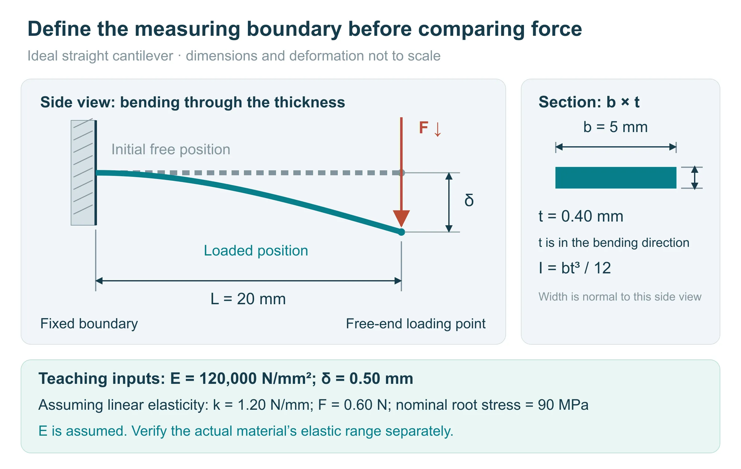
Initial curvature, a formed root or multiple contact points can change the contact location and lever arm under load. Overall part length cannot simply be substituted for L. Establish the actual support and loading arrangement before choosing a suitable calculation, simulation or representative-part measurement.
Total assembly travel may also differ from spring deflection: there may be clearance before contact, followed by sliding, friction or mating-part deformation. Assembly force measured in the insertion direction is not automatically the contact normal force. Compare the same type of force at the same functional position and along the same loading path.
3. A reproducible example shows how geometry changes force
Teaching calculation only: assume linear elastic response with E = 120,000 N/mm²; L = 20 mm, b = 5 mm, t = 0.40 mm and δ = 0.50 mm. E is an assumed input, not a measured value for C7701 or any purchased material. Use a small-deflection straight-beam model, neglecting shear deformation, local radii, residual stress and fixture compliance.
The rectangular second moment of area is I = bt³/12 = 0.026667 mm⁴. Tip deflection is δ = FL³/(3EI), giving stiffness k = F/δ = 3EI/L³ = 1.20 N/mm and force F = 0.60 N at 0.50 mm deflection. Use N for force, mm for lengths and N/mm² for E; do not insert a numerical GPa value directly. MIT’s bending-deflection notes, page 268 give the displacement equation for these boundary conditions.
Maximum nominal root bending stress is σ = 6FL/(bt²) = 90 MPa; here δ/L = 2.5%. Small deflection does not establish elastic material response: check evidence for the selected material in its condition after processing. Nominal stress also excludes local concentration at notches or root details. The University of Illinois beam-bending notes explain the relationship between second moment of area and elastic bending stress.
Changing one dimension at a time while retaining the same E and δ produces the following results. These are model calculations, not recommended tolerances or material selections.
| Single change to the model | Stiffness k (N/mm) | Force at δ = 0.50 mm (N) | Nominal root stress (MPa) |
|---|---|---|---|
| Baseline: L = 20, b = 5, t = 0.40 mm | 1.200 | 0.600 | 90.0 |
| Thickness changed to 0.44 mm; otherwise unchanged | 1.597 | 0.799 | 99.0 |
| Effective length changed to 22 mm; otherwise unchanged | 0.902 | 0.451 | 74.4 |
| Width changed to 10 mm; otherwise unchanged | 2.400 | 1.200 | 90.0 |
Under these assumptions, stiffness varies with thickness cubed and inversely with effective length cubed. A slightly deeper clamp or changed sheet thickness can therefore substantially change force. Increasing width raises total force but does not reduce nominal root stress in this displacement-controlled model. Increasing thickness raises both force and stress at the same deflection. Recheck force and stress together after a dimensional change.
4. Returning after release does not prove every stroke is recoverable
Two tempers with similar actual elastic modulus and identical geometry can have similar force–deflection slopes within their shared linear elastic range. Their usable stress or displacement range may differ. Do not extend that straight line indefinitely to predict force outside the applicable range.
The commonly reported Rp0.2 is proof strength at a specified plastic extension, not a strict zero-permanent-set limit. For a spring that must return accurately, calculated stress below Rp0.2 alone does not prove absence of permanent set. Agree finished-part residual-displacement limits and measurement resolution. Materion’s explanation of near-elastic properties distinguishes elastic limit, proof strength and spring bend limit.
Record the initial free position, load through the agreed stroke, unload completely and remeasure the same point after a specified waiting time. Separate working stroke from maximum assembly stroke: a single overtravel while passing a locating feature can change subsequent free position and contact force. Agree beforehand whether samples used for overtravel checks will enter other tests, so that loading histories are not mixed.
5. Check force after prolonged deflection at a defined temperature and position
Stress relaxation concerns force decreasing with time while deformation is maintained. It can occur below the commonly specified yield strength. Alloy, temper, initial stress, temperature and time all affect the result, so one hardness reading or initial force measurement cannot predict long-term retention. Materion’s stress-relaxation article explains these factors.
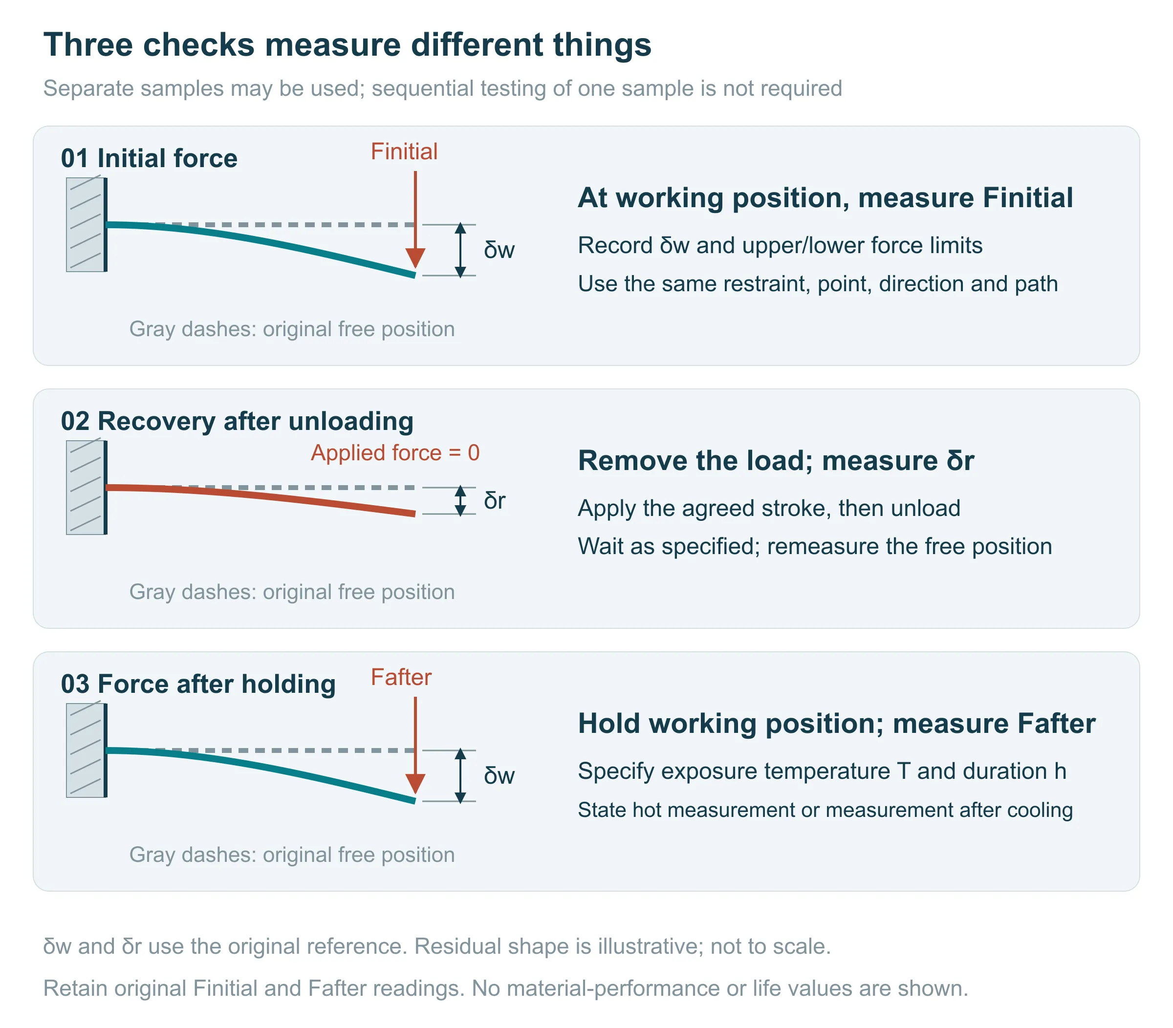
Record the held working position, exposure temperature, duration and whether force is measured in place while hot or after cooling to a specified temperature. These results have different meanings and cannot be combined as one metric. Thermal deformation of fixtures or plastic supports can also change actual spring displacement. When force decreases, check restraint and contact position as well.
If a retention percentage is specified, define it as Fafter/Finitial × 100% on a consistent measurement basis and retain both original force readings. High retention with inadequate initial force may still fail the function; simply increasing initial force may create excessive assembly force. Acceptance should also specify minimum post-test force, with limits determined by the application.
6. Repeated operation and continuous holding need different evidence
Repeated opening, mating or vibration introduces cyclic loading. Passing one loading test does not demonstrate freedom from later fatigue cracks; cyclic stresses below yield strength can still cause fatigue damage. Assess notches, cut edges and forming damage alongside the actual cycling conditions. Materion’s fatigue-failure explanation distinguishes cyclic damage from single loading.
Specify starting and ending displacement, cycle count, frequency, temperature and intermediate inspections, together with criteria for cracks, residual position and force changes. Electrical contacts also require application-appropriate checks of mating surfaces and electrical function. “No breakage after the specified cycles” does not automatically establish acceptable contact function. Holding and cycling tests may be combined in a plan, but conditions and sample loading history must remain explicit; neither test replaces the other.
7. Separate material records from finished-part acceptance, then link both to the sample batch
Record alloy, product standard, delivery condition, thickness and orientation when ordering material. For finished-part approval, check results after the actual forming, heat treatment, joining and surface-treatment route. Hardness readings also need the method, scale, test force and location; avoid ranking numbers obtained under different measurement conditions.
Confirm material condition together with the processing route. A temper suited to carrying load may not suit the proposed bend. Forming before treatment and forming strip that was strengthened beforehand are not equivalent merely because final hardness is similar. Review bend damage, dimensions and final function, but do not prescribe a heat-treatment temperature without specific alloy data. For material families and candidate alloys, see nickel-silver selection and copper and brass selection.
| Handover item | Specify in the order or sample plan | Corresponding evidence |
|---|---|---|
| Material identity and condition | Alloy, applicable standard, temper, thickness, tolerances, rolling direction and batch | Traceable material records; mechanical-property checks as agreed |
| Initial finished-part function | Drawing revision, restraint, free position, working-displacement range and force limits at each position | Representative-part loading records, fixture and measurement-point descriptions |
| Recovery after release | Working and maximum assembly strokes, waiting time after unloading, residual-displacement limit | Position of the same point before and after loading |
| Holding and cycling | Temperature, time, cycling range, count, measurement timing, acceptance limits and sampling plan | Original data for the identified samples and post-test functional records |
Environmental declarations, RoHS/REACH reports and SDS documents serve their own purposes; they do not establish spring force, fatigue or stress relaxation. For a designation such as C7701, still check the governing standard and condition rather than assigning another grade’s properties based on a similar name.
If only a sketch or an old sample is available, mark the restraint, contact location, maximum assembly movement, service temperature and operating motion. Mark an undecided force value “to be confirmed on samples”. Use these real functional conditions to discuss material and geometry, then record the accepted result in the drawing and inspection plan.