1. A cut-to-length product description is not a complete acceptance requirement
A typical cut-to-length line combines uncoiling, leveling, shearing and stacking. These functions turn continuous strip into sheets of the required length. Cutting to length and leveling are therefore not mutually exclusive options. Ask which operations the supplied material actually underwent. [1]
Leveling may be performed on coil strip or separately on sheets or parts after cutting. Equipment, operations and objectives vary with the processing route. Terms such as “precision cut-to-length” or “leveled” do not prove identical processing or conformity of the eventual finished part. [2]
| Operation | Main purpose | What still needs checking at receiving |
|---|---|---|
| Uncoiling and feeding | Open the coil and feed subsequent operations | Coil identity, surface orientation and handling or feed damage |
| Leveling | Improve shape using a process suited to the material and incoming shape | Material and size range, resulting shape, surface and downstream requirements |
| Cutting to length | Divide continuous strip into agreed sheet lengths | Length, width, cut edges, squareness and shape after separation |
| Stacking and packing | Support handling and delivery while retaining material identity | Sheet-to-label links, support and restraint, wetting and local damage |
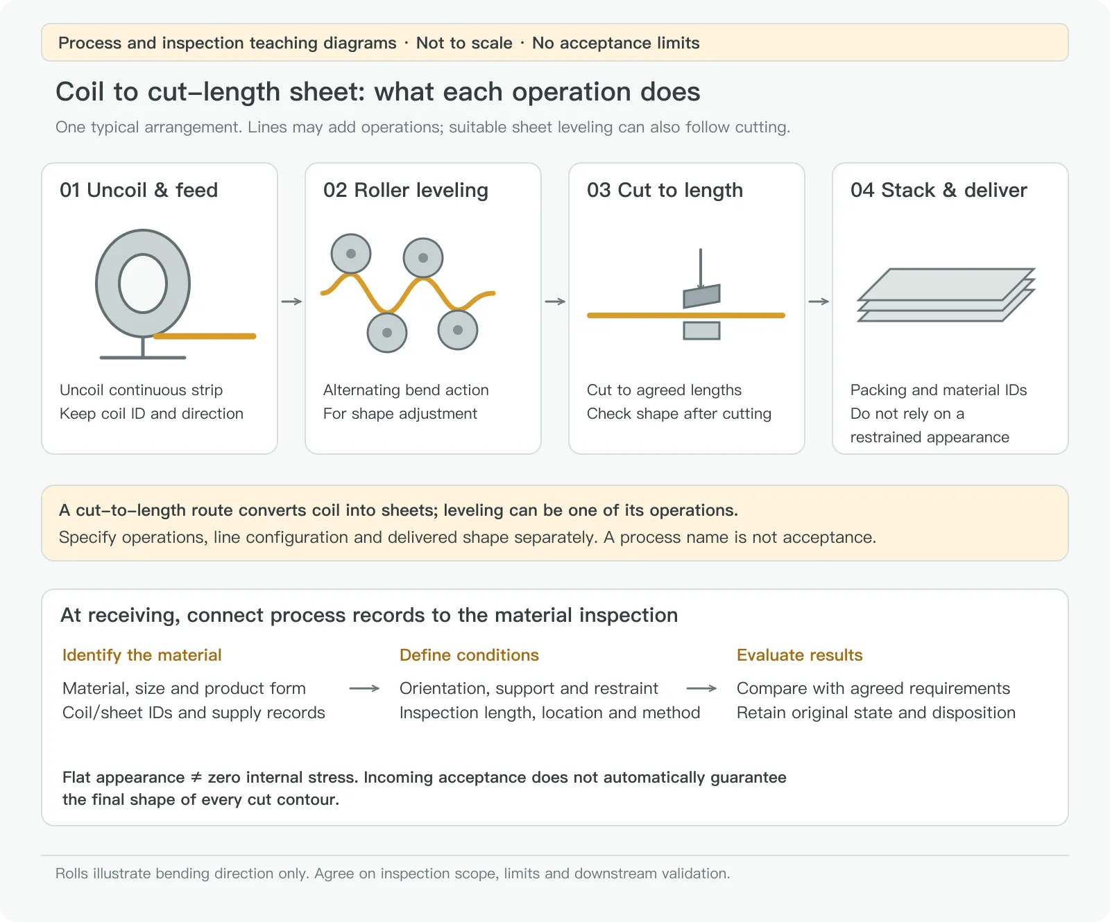
Specify the processing description separately from the delivered-product requirements. In addition to ordering cut-length sheets, define material, dimensions, shape, surface and inspection basis. If the sheets will become large-window panels, narrow strips or mating surfaces, share those uses so that any necessary downstream-processing validation can be discussed.
2. Establish length and width directions before naming the shape
Preserve a traceable orientation mark before inspecting. Here, L is sheet length and W is sheet width. Only identify L as the original coil’s longitudinal or rolling direction when records support that relationship. Rotation, nesting and further cutting can change how the finished sheet dimensions relate to the original material axes.
Coil set, also called longitudinal bow, is a tendency to curve along the original strip’s length. Crossbow is curvature across its width, with an arched transverse section. Edge wave occurs near the edges, while center buckle presents as waves or pockets in the central region. More than one condition can occur together. [3]
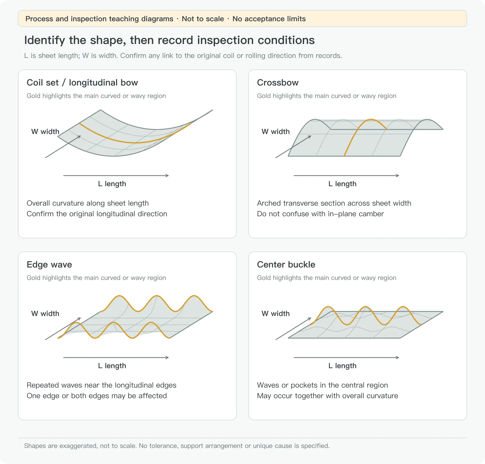
Edge waves and center buckles can describe visible consequences of length differences across the strip width. Their appearance alone does not identify one machine or setting as the cause. Review rolling, subsequent processing, leveling and handling records as relevant. In-plane sideways curvature of a longitudinal edge—camber—should not be confused with crossbow across the sheet width. [3]
3. Leveling is not a certificate of zero residual stress
Roller leveling uses alternating bending between adjacent rolls, generally with decreasing bends toward the exit. With suitable material, geometry and equipment conditions, it can improve shape and affect the internal stress distribution. Results depend on the workpiece and settings; a machine supplier’s description is not a guarantee for every sheet. [4]
Residual stresses can exist without an external load. A visually flat surface and its internal stress state are different matters. Removing material, creating a new contour or applying heat can alter the existing balance. Conversely, a warped shape does not by itself establish residual stress as the sole cause. [4]
Verify incoming-sheet shape, the performance of an agreed processing test and finished-part assembly requirements separately. If the purchase requirement includes shape after cutting, agree on specimen location, contour, processing conditions, support and evaluation scope beforehand. A casually cut sample cannot establish a guarantee for an entire coil or every possible part.
4. Align inspection conditions before comparing readings
Record the original packing and stacking arrangement before removing the inspection sheet under appropriate handling procedures. Use suitable lifting and support for large or sharp-edged material. Do not press on hazardous locations to make the sheet appear flat. Link the selected sheet to its heat, coil or receiving identity and distinguish inspected sheets from the remainder.
Keep the inspection surface and supports clean. Debris, burrs or misplaced spacers can raise a local area. Record which face is up, the length and width directions, support locations and any remaining straps or clamps. Flexible sheet responds to self-weight and orientation. Observations on two support bars and on a continuous surface should not be treated as directly comparable before-and-after results. Record free and restrained states separately. [5]
A straightedge and feeler gauge can help locate gaps near a defined inspection line. Record straightedge length, position, contact arrangement and reading location. Do not press the straightedge or sheet to obtain a smaller number. If results change substantially after lifting and replacing the sheet, investigate support, contact and operator repeatability first.
A sheet product specification’s flatness test may use a different scope or evaluation procedure from a finished-part geometric flatness requirement. Geometric flatness concerns containment of the inspected surface between two parallel planes at a specified separation. One local straightedge gap does not cover that surface. Establish the ordered requirement before selecting the measurement method. [6]
5. Use the observed shape to choose the next check
The following table is an investigation sequence, not a visual pass/fail standard.
| Observed condition | Conditions to record first | Next point to establish |
|---|---|---|
| Overall lengthwise bow | Orientation, upper face, inspection length and support locations | Relationship to the original coil direction and comparable sheets from the lot |
| Arched shape across width | Transverse inspection line, actual width and contact at edges and center | Crossbow versus lifting from a spacer or inconsistent support |
| Repeated waves near an edge | Which edge, crest locations, local and overall shape | Wave height, spacing or other information required by the applicable method, followed by material and processing records |
| Waves or pockets in the center | Affected region, surrounding contact and any overall bow | Center buckle, local damage or overlapping shape conditions |
| Flat in a bundle, uneven after removal | Straps, sheet position and support before and after removal | Whether the original state was restrained or handling added deformation |
| Flat incoming sheet, distorted cut part | Original sheet location, cut contour, post-cut support and cooling state | A separate cutting-process investigation, retaining both incoming and post-cut evidence |
Interpret readings with the ordered product specification and edition, thickness and dimensional range. Product forms may have different shape tolerances and manufacturer guarantees. For example, a mill may distinguish plate, hot-rolled sheet and cold-rolled sheet within one product family. [7] Do not borrow a convenient limit from another grade, brand or width table, or invent a universal allowance per meter.
6. A hypothetical receiving comparison
Suppose two records describe one batch of cut-length sheets. One says “visually flat while strapped”; the other says “long-edge waves after removal.” The inspected material might be the same, but the conditions are different. These are teaching conditions, not customer test results.
Identify the sheet, face and orientation, then recheck under the same agreed support arrangement. Keep unpressed photographs and relate each reading to its inspection line and location. If the original records lack sheet identities, do not treat observations from different sheets as a before-and-after comparison of one sheet.
Only then compare results with the agreed product requirement. If the order merely says “cut to length, good flatness” without an executable inspection basis, clarify the requirement and control material awaiting review under the applicable procedure. Do not select whichever standard happens to produce a pass afterward.
Before additional leveling, the responsible process personnel should evaluate material condition, size, surface requirements and downstream use, then arrange representative validation. Recheck shape, dimensions and surface after the additional operation. A photograph taken while the sheet is pressed flat does not complete that review.
7. Share records that explain how the sheet was inspected
A useful receiving record connects material identity, order requirements, selected sheet, orientation and support, method and locations, observations and disposition. Include orientation, location and a scale reference in photographs, using the same identifiers in the written record. An unidentified close-up rarely explains the condition of the full sheet.
For a processing discussion, share the material and dimensional requirements and incoming photographs. Mark the intended mating surface, window or narrow-strip region. If flatness requirements are not yet decided, describe the use first. Separating incoming-material requirements from downstream needs makes it easier to agree on supply and validation arrangements.
- [1] Shapeline — Cut-to-length Lines
- [2] ARKU — Coil Processing Lines
- [3] WorldAutoSteel — AHSS Guidelines, Coil Shape Imperfections Influencing Roll Forming
- [4] ARKU — Smooth operations thanks to leveling
- [5] KEYENCE — GD&T of Non-Rigid Parts
- [6] KEYENCE — Form Tolerance: Flatness
- [7] SSAB — Hardox 450: Tolerances, Shape and Flatness