1. Record when the shape changes before assigning a cause
Keep the same part identification, face markings, position in the original sheet and cutting direction. Record the incoming shape under clearly identified support conditions, then use the same markings after cutting. If clamps, hold-downs or retaining microjoints are used, record when they are released. Ordinary sheet laser cutting may rely mainly on table support; it should not always be described as clamped cutting.
The laser heats material locally until it melts or vaporizes, and assist gas removes material from the kerf. It does not apply the broad contact loads of conventional tooling, but it still introduces heat. Non-contact cutting does not rule out thermal distortion. [1]
Distinguish overall bowing, local edge waviness and a change in the position of the whole part as one end tips up. A small part tilting after losing support does not necessarily mean its material has permanently bent. Support during cutting and removal affects tipping risk, which is one reason machines may incorporate dedicated support and unloading mechanisms. [2]
2. Separate heat input, residual stress and part geometry
Material near the kerf heats first, while cooler surrounding material restricts its expansion. Cooling then changes local dimensions and stresses again. Uneven temperatures can cause bending or twisting. Concentrating cuts in one area, or changing contours and nesting, changes heat distribution. The final direction of warping alone cannot establish that power was too high or speed too low. [3]
Residual stresses remain within material without an applied external load. They may originate in earlier manufacturing operations. Cutting a contour or removing a large region changes the existing balance, and the shape may change with it. A sheet that looks flat can still contain such stresses, while warping alone cannot prove that residual stress is the only cause. [4]
A long strip, a narrow frame around a large cutout and a small solid panel from the same sheet do not have equivalent geometry. Their remaining material, support spans and constraints differ. Areas where deformation is more apparent deserve attention, but there is no universal width below which every part must warp. Review the actual thickness, material, contour and use.
3. Keep comparable records at four stages
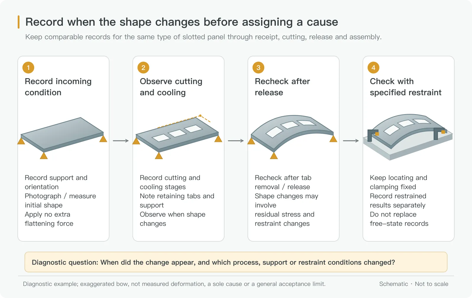
Incoming material: observe the sheet on recorded supports and in a recorded orientation. Check the surface, edges and underside for foreign material. Do not press it flat before photographing it and hide its initial shape. Retain material and batch records, and mark where the part comes from in the original sheet.
Cutting and cooling: use observation methods permitted by the equipment to record the contour and moment at which a change appears. Distinguish active heating, cutting completed before cooling, and the agreed measurement condition. Record the program revision, cutting sequence, support and remaining connections together. Do not treat a hot-state reading as the final acceptance result.
Tab removal or unclamping: compare the state before and after releasing microjoints, hold-downs or clamps, then check whether unloading or handling introduces bending. If the part was not clamped, record its separation from the scrap skeleton and changes of support rather than inventing an unclamping step.
Assembly: check fit using the agreed locating conditions, tightening sequence and relevant loads, and report it separately from the state without those restraints. If the issue appears only after welding, bending or fastening, investigate that operation rather than attributing every change to laser cutting.
4. Use the observation to choose the next check
The factors below are possibilities to test. An observation can narrow the investigation, but it cannot establish a cause on its own.
| Observation | Possible factors | Next check |
|---|---|---|
| Before cutting, readings change when the sheet is repositioned | Incoming shape, support position, gravity or foreign material underneath | Clean contact areas, repeat placement on the same supports and in the same orientation, and retain incoming-sheet records |
| Local waviness increases while one area is cut repeatedly | Local heat accumulation, cutting sequence and contour density | Compare program timing with the cooled condition, then make a controlled cutting-path comparison |
| The frame changes shape after a large opening or outer contour is cut | Residual-stress redistribution and changes in geometric stiffness or restraint | Identify the last contour cut and compare repeat parts of the same material and geometry |
| One end of a small part tips up, but the part itself is not bent after removal | Insufficient support or tipping after separation from the skeleton | Inspect cutting-bed support and removal movements; separate whole-part tipping from material warping |
| The part sits flush while held down, then lifts after release | Restraint conceals the free shape, or equilibrium changes after release | Record results without added flattening force separately from results under the specified restraint |
| A gap or rocking appears only on the side resting on an edge | Burrs, dross or support debris lift the part; genuine deformation may also be present | Inspect and record contact points, then clean as specified and remeasure; do not assign the entire gap to warping |
| The cooled cut part looks normal but changes after tab removal or handling | Tab-removal method, gripping position or stacking loads | Compare before and after unloading; check whether a weak frame is pried, pressed or poorly supported |
| Free shape changes little, but assembly gaps become uneven | Mating parts, locating conditions, tightening sequence or joints | Check both mating parts and assembly conditions, and report assembled gaps separately |
Burrs and dross are edge issues that may affect contact readings and may also need separate treatment. Keep records before and after cleaning. If deburring itself can change a thin part's shape, observe it as a separate operation. For edge requirements, see the sheet-metal deburring and edge-acceptance guide.
5. Free state, restrained state and flatness are different questions
A free-state check needs defined supports, orientation and consideration of gravity. Avoid flattening the part with a hand, a hold-down or probe force. Placing sheet on a table does not automatically create a suitable free-state setup: table contact and deformation under the part's own weight still affect the observation. For a restrained check, specify locating points, clamp positions and sequence, and relevant force or torque conditions. [5]
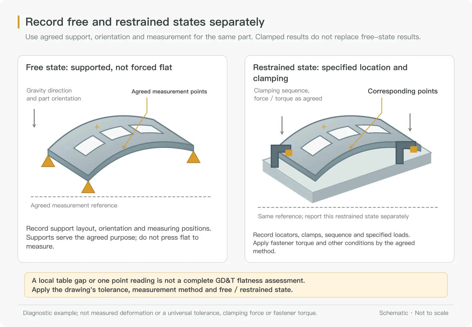
A straightedge and feeler gauge can quickly reveal a gap near a particular inspection line; that reading is not automatically the flatness of the entire surface. Support, sampling coverage and evaluation affect the result. Formal flatness inspection should follow the drawing's rules, using suitable measurement coverage and evaluation to determine whether the surface lies within the specified pair of parallel planes. [6]
Describe records directly as a reading at a defined inspection line or point under stated support conditions, or identify the flatness measurement method used. If repeat unloading and placement significantly change the result, investigate restraint, contact and measurement repeatability before deciding that the part is out of tolerance. Limits come from the drawing and agreed acceptance conditions, not from a photograph of a warped part.
6. Diagnostic example: flat after cutting, but a frame edge lifts after removal
Assume a thin steel panel has a large central cutout and retains microjoints during cutting. After cooling and removal, one long edge lifts. This is a diagnostic example with hypothetical observations, not a measured customer case.
| Stage | Hypothetical record | What this establishes |
|---|---|---|
| Incoming material with support and orientation recorded | Shape at the inspection locations is broadly consistent after repeated placement | An incoming baseline; it does not prove that residual stress is absent |
| After cutting and cooling, with microjoints retained | The panel does not visibly lift in the scrap skeleton | Only the shape at this temperature and connection state |
| Connections removed using the recorded method; part placed on inspection supports | The same long edge lifts repeatedly | Prioritize release, unloading and stress redistribution; the thermal process has not yet been ruled out |
| Fixed under the specified assembly conditions | The long edge sits flush, but the joint gap changes after tightening | An assembly result; it cannot replace free-state acceptance |
For the next trial, hold material batch, thickness, contour, original-sheet orientation, cutting parameters, cooling conditions and inspection supports constant. Compare only one tab-removal or unloading method and see whether the change repeats. If cutting sequence is to be compared, run a separate trial with the unloading method unchanged. Changing material, path and fixture together cannot show which change mattered.
If the revised process gives a more stable free shape, recheck hole positions, cut edges and final fit. Without remeasurement, looks flatter cannot be reported as meeting the flatness requirement. If repeat parts differ, retain those differences and continue checking original-sheet location or process variation.
7. Let the evidence guide the corrective action
When the relationship between local heating and cutting timing is clearer, process personnel can evaluate cutting in distributed areas, contour sequence or other suitable options, while also checking cut-edge quality. Where support or unloading has the stronger effect, compare those positions and movements first. If incoming stress is suspected or leveling is needed, trial the actual material, geometry and subsequent forming; a flat appearance after leveling does not establish that every internal stress has been eliminated.
Changing settings, leveling or heat treatment is not a universal first step. In particular, do not apply another steel grade's heating temperatures or cooling practices simply to address warping. If the change begins during later welding, use the thin-sheet welding distortion guide. If dense punching causes the change, the dense-perforation and sheet-shape guide covers that mechanism.
When discussing a fabrication plan, provide the drawing, material and thickness, original-sheet location, photographs before and after cutting, and records of when the part lifted, how it was supported and whether it was held down. If flatness or assembly-gap limits are undecided, explain which face must sit flush and which holes must align. Defining the inspection state and acceptance conditions around the actual use is usually more helpful than changing a material name first.