1. State the bend-line relationship to RD before using “with the grain”
Rolling direction, RD, is the direction of material travel during rolling. The bend line marks the bend position on the flat pattern and runs along the bend axis; it is different from the motion of the flange as it rises. In a local section through a simple straight bend, the outer layers are in tension and the inner layers in compression. The principal tensile extension at the outside is perpendicular to the bend line.
“Bending along RD” can mean two different things: a bend line running along RD, or material being curved and stretched along RD. Those axes differ by a right angle. JX Advanced Metals calls a copper-alloy bend with its axis perpendicular to RD a Good Way bend; Materion's copper-strip guidance uses longitudinal for its Good Way direction. When reading data from different suppliers, check the orientation diagram and test definition instead of translating one word alone. JX Advanced Metals: bend direction; Materion: copper-alloy strip formability.
| Direction to establish | What to put on the drawing or record | What cannot replace it |
|---|---|---|
| Material rolling direction | RD arrow, its source and the associated parent-material ID | Part long edge or machine feed direction |
| Each bend line | An identifier such as A or B and its relationship to RD | Only “with-grain” or “across-grain bend” |
| Outside of the bend | Which face becomes the tensile outer face in this operation | Only the front or cosmetic face of the whole part |
| Decorative direction | Meaning of brushing, texture or film arrows | Treating it as RD without the supplier's confirmation |
2. Relate one direction diagram to two bend cases
Assume RD runs along X in a flat sheet. Bend line A runs along Y, so A is perpendicular to RD; bend line B runs along X, so B is parallel to RD. For the simple straight bends shown, the outer layers at A extend mainly along X, while those at B extend mainly along Y. This illustration compares directions only; it specifies no material, radius or passing result.
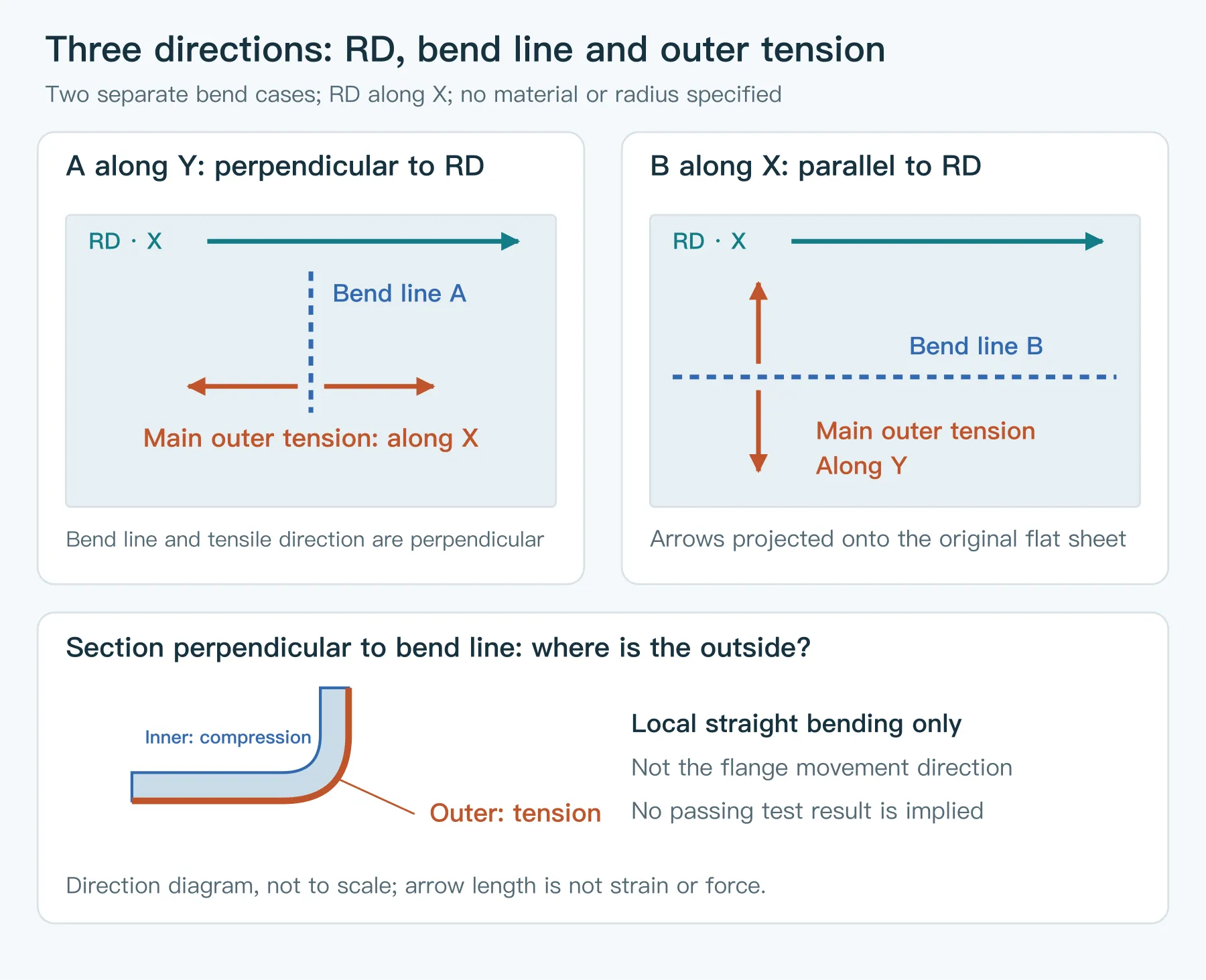
Rolled material may have different plastic deformation behavior in different directions; this directional variation is called anisotropy. The amount of cold work can affect directionality in copper strip. Better formability in one direction does not mean the other direction cannot be processed at all. Base the decision on data for the actual grade and temper and verification representative of the part.
SSAB recommends a bend line transverse to RD where possible for its special steels, but its Strenx strip guarantee table also lists products with the same final inside-radius requirement in both directions. That guarantee also specifies product, thickness and bending conditions. “Perpendicular to RD is always better” therefore cannot be applied to every steel, aluminum or copper alloy, and a high-strength steel's radius multiples cannot be transferred to ordinary thin sheet. SSAB: preparing special steels for bending; SSAB: Strenx bending guarantees and conditions.
3. Identify the axis described by L and T in a material report
In sheet tensile testing, L usually means the tensile-specimen axis is parallel to RD, while T means that axis is perpendicular to RD within the sheet plane. RISE's sheet-testing description uses longitudinal, transverse and diagonal specimens relative to RD. These describe sampling and loading directions, not the bend-line direction of a part. RISE: tensile testing of aluminum sheet.
In Figure 1, the principal outer tensile direction at A aligns with the axis of an L tensile specimen, although bend line A itself is perpendicular to RD. This correspondence only identifies direction. A uniaxial tensile test is not equivalent to a bend test, and elongation does not directly determine a usable bend radius for the part.
For a “longitudinal/transverse bending” table, establish whether its headings refer to specimen length, tensile direction or bend axis. Asking the supplier to sketch RD, the specimen and the bend line is often clearer than discussing “grain direction.” Before comparing tables, also align grade, temper, thickness, specimen width, bend angle, test method and surface assessment criteria. Record roughness, orange peel and observed cracks separately. KME: Copper Materials, page 52, bending evaluation.
4. Carry direction through slitting, nesting and blank handling
Establish the RD evidence for the parent coil or sheet, then transfer it to slit coils, cut-to-length sheets, blanks and reusable remnants. Marks may be placed on process margins, labels or controlled nesting drawings, but must correspond to the actual material and avoid scratching critical surfaces or bend zones. Parent-material identity tells you which batch it came from; RD tells you its orientation. Both are needed for their separate purposes.
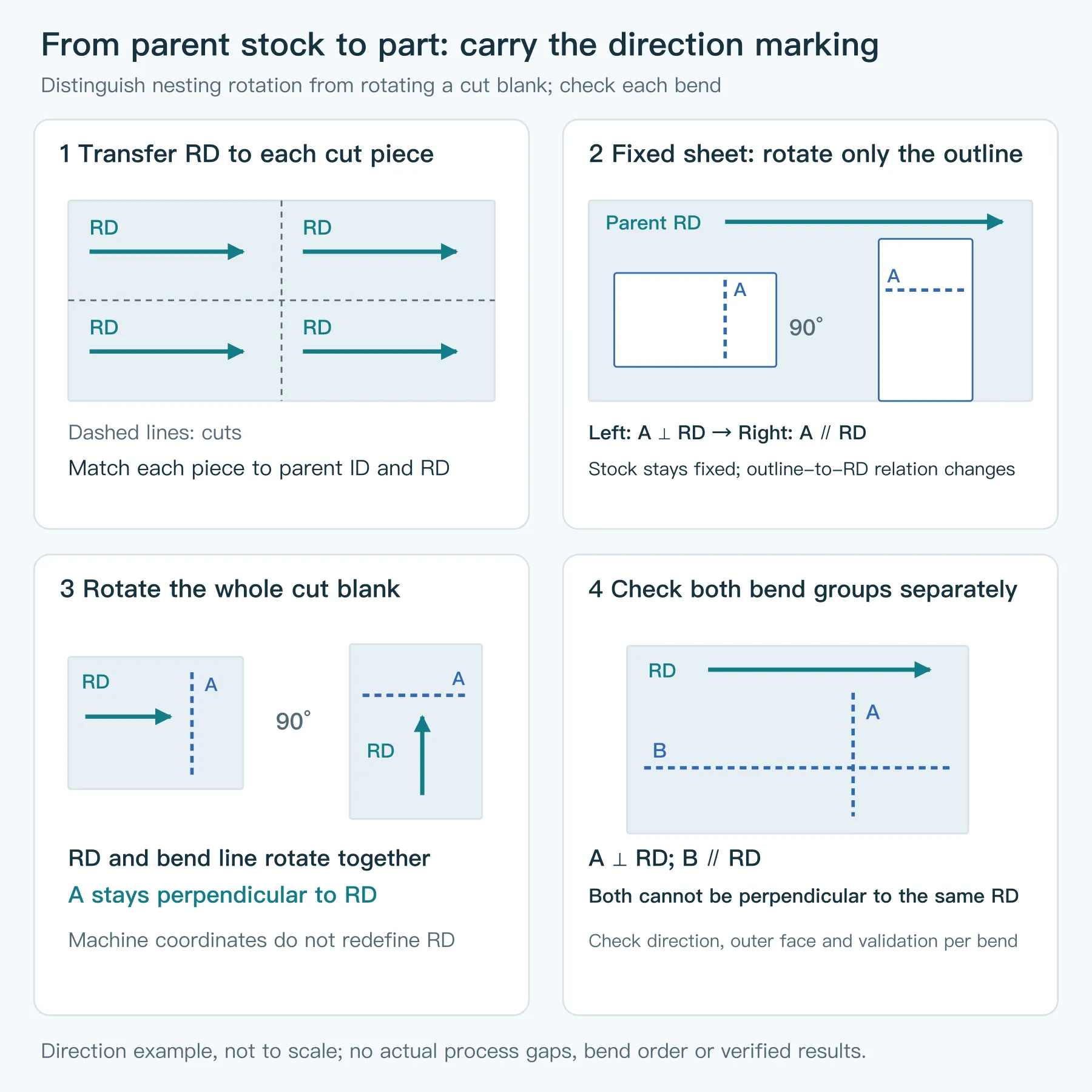
Rotating a part outline by 90° on a stationary parent sheet can turn a bend line perpendicular to RD into one parallel to RD. After the blank is cut, rotating the entire blank by 90° also rotates its material direction, leaving the angle between the bend line and RD unchanged. A new loading position at the machine does not justify drawing a new RD arrow along the machine's long axis.
When one part has two perpendicular groups of bend lines, both groups cannot be perpendicular to the same RD. Check each separately instead of writing “all bends across the grain” for the whole part. Diagonal nesting only changes the angles of the lines; it does not establish that both groups will form successfully. If needed, compare changes in material temper, local geometry or process.
| Direction example: RD along X | Relationship on the flat pattern | Question for process review |
|---|---|---|
| Bend A, line along Y | A perpendicular to RD | Do the outer surface and cut edges at both ends meet requirements with the chosen material and tooling? |
| Bend B, line along X | B parallel to RD | Is there material evidence and representative verification for this direction? |
| Rotate the whole outline 90° on the parent sheet | A and B exchange their relationships to RD | Does the new nest still meet the confirmed conditions for each bend? |
When direction is unknown, record “RD to be confirmed” and trace supply markings and cutting records. Sheet length, brush marks and protective-film arrows do not automatically establish RD; use an arrow only after its meaning and transfer history have been confirmed. Trials in two directions can compare this batch's behavior, but the easier-bending direction alone cannot reveal its true RD.
5. Test whether direction contributes to cracking
First locate where cracks begin: the middle of the outer bend surface, cut edges at either end, a hole edge or an existing scratch. Surface damage, edge condition and tooling setup also affect cracking. If cutting method, burr-side orientation or material batch changes along with direction, the result cannot be attributed to RD alone.
One comparable checking plan uses two sets of geometrically identical specimens from traceable material with known RD, changing only the bend-line relationship to RD. Hold material temper, thickness range, surface orientation, edge preparation, tooling and forming settings constant; clearly record differences when actual conditions cannot be matched. Agree specimen quantity, inspection method and acceptance criteria beforehand.
| Comparison record | Set A: line perpendicular to RD | Set B: line parallel to RD |
|---|---|---|
| Parent material, grade, temper and measured thickness | Enter actual records | Check comparability |
| Tensile face, cutting method and burr condition | Enter actual records | Keep identical or state differences |
| Tooling, bend settings and unloaded shape | Record tooling and measured angle and inside radius | Record results on the same basis |
| Outer bend surface, both end edges and existing marks | Record locations, photos and inspection conditions | Inspect by the same method |
| Result and applicable scope | Complete against agreed criteria | State whether it supports this part orientation |
This is a blank record format, with no predetermined passing set. Repeated differences consistent with orientation under controlled conditions provide stronger grounds for identifying direction as an influencing factor. If both sets crack at similar cut edges, continue investigating edge and local forming conditions. Even if changing orientation removes the cracks, verify the other bends and assembly requirements in the finished geometry.
6. Carry the approved orientation into the next material batch
After sample approval, retain grade and temper, RD evidence, flat-pattern revision, permitted nesting rotations and verification records for each critical bend together. Recheck those conditions when replenishing stock, changing coil, using remnants or revising a nest. A photo of a conforming sample alone cannot show whether the next batch of blanks has the same orientation.
Use the sheet-metal bending DFM guide for flat-pattern calculations and tooling geometry, and the steel sheet size and nesting quote guide for purchased quantities and utilization across stock sizes. First establish how the part may be positioned and which material direction corresponds to each bend line.
If RD is still unconfirmed, start with a part drawing, sketch or crack photos. Mark the crack location, known material and application, and identify missing temper or direction information as unconfirmed. Checking a specific location and process conditions gives a clearer next step than asking only whether the sheet cracked “with the grain.”