A mechanism can move every component to its intended endpoint yet still fail at the handoff between actions. Reviewing the whole cycle helps engineering and purchasing teams distinguish a motion demonstration from evidence that a particular part can be handled repeatedly under agreed production conditions.
How does a cam put continuous motion into an ordered sequence?
Consider a rotating cam. As the shaft turns, a roller or other follower tracks its profile to produce translation or oscillation. The profile determines when the follower moves, how far it travels, where it dwells and when it returns. Carnegie Mellon University's mechanisms text describes a cam cycle in terms of rise, dwell and return. [1]
During dwell, the input continues moving while a particular follower holds its designed position. This leaves time for another action: the feed axis can wait while the part lifts clear of a locator, or remain at the next station while the part is lowered and released.
Arms, links and guides also shape the output. Their geometry affects actual gripper travel, so a change in cam profile height is not necessarily equal to workpiece displacement.
A mechanical design may use separate cams or motion branches for feed, lift and gripping. Their phase relationships to a common input set the sequence. Seeing one cam does not establish that it generates every action on its own.
Read a transfer cycle as six handling actions
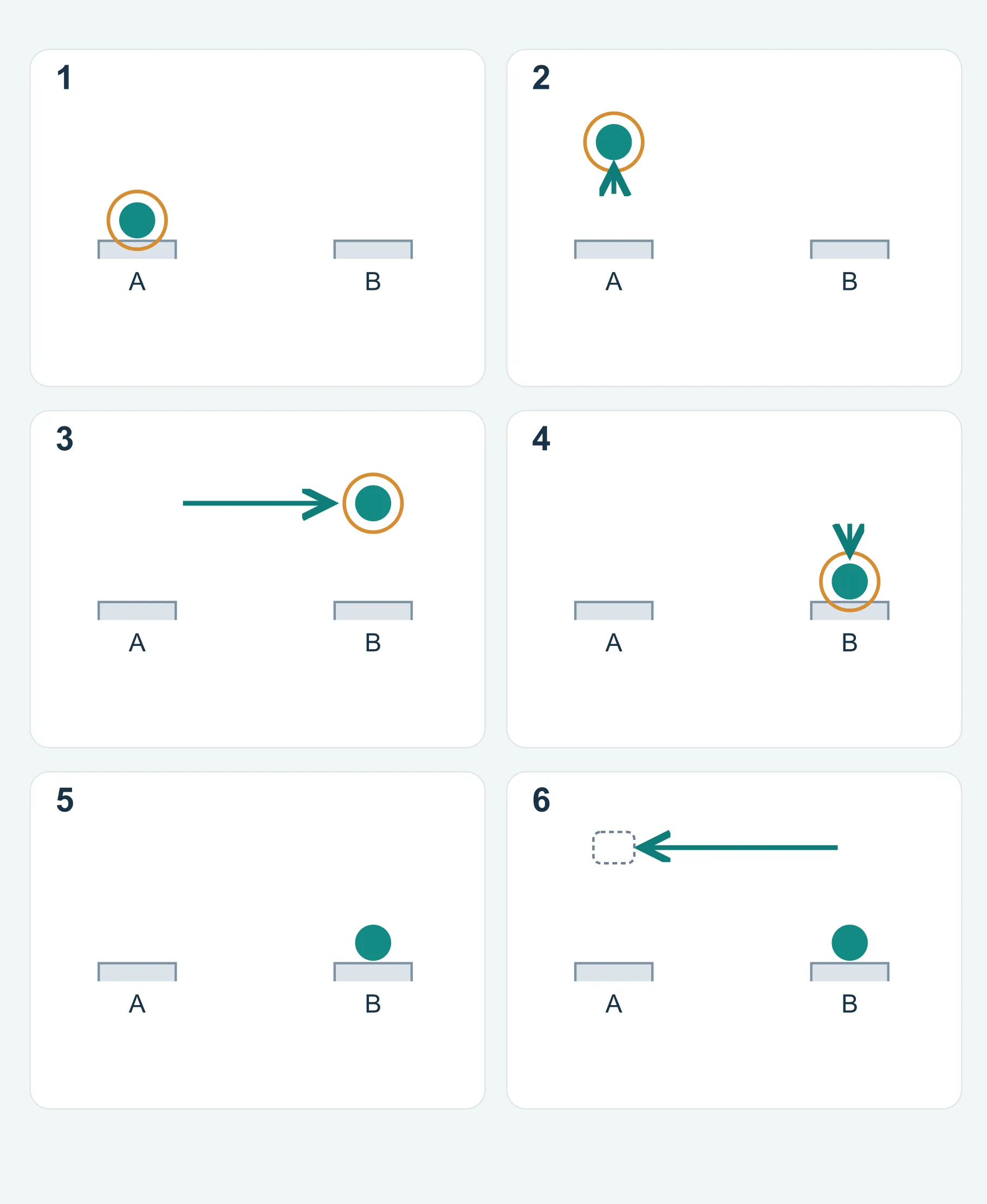
For a transfer with gripping, lifting and feeding, distinguish travel along the stations, vertical travel and gripper approach or withdrawal. This guide calls these X, Z and Y respectively; equipment axis names can differ.
The six separate actions below explain the handling logic. Real mechanisms may overlap actions after interference checks, and vacuum, magnetic or other gripping arrangements may follow different paths. AIDA lists feed pitch, lift stroke, clamp timing and upper-die clearance functions separately: these items need a coordinated review. Its cited NCAH III system is servo-driven. [2]
For some opposed-gripper layouts, opening the grippers creates part of the clearance. Others need additional vertical or lateral escape. Check the empty return independently; a clear forward path with the part does not establish a clear return path.
| Action | What moves or holds | Check before continuing |
|---|---|---|
| 1. Grip | Grippers enter the pickup position and establish a secure hold. | The preceding forming operation has released the part; the grip will not slip or damage a critical surface. |
| 2. Lift | The part leaves the lower-die support, locator or cavity. | Locators and formed features are clear of the transfer path. |
| 3. Advance | The held part travels to the next station. | The complete swept envelope of the part and grippers clears dies, pressure pads and neighboring parts. |
| 4. Lower | The part enters the next station's support and locating features. | It is supported securely and oriented for the next operation. |
| 5. Release | Grippers release and move away from the part. | Release will not drag, lift or displace the seated part. |
| 6. Return | The empty mechanism follows its designed clearance path back. | The part remains at the destination and the mechanism reaches its specified safe position before the subsequent die closing. |
Why dwell and phase matter more than smooth-looking movement
Actions that work individually can fail when joined. Lifting before the grip is secure can drop a part; feeding before clearing a locator can cause a collision; releasing before reliable seating can lose the next station's position.
Plot press-slide motion, pressure-pad or ejector motion and each transfer action on the same time or master-angle axis. Check handoffs as well as endpoints: how far must one action progress before the next may begin?
An open upper die is only one condition. The part must be extractable, holding elements must release it and the entire part-and-gripper path needs clearance. The available window depends on the tooling and equipment; one fixed angle schedule cannot serve every transfer die.
Mechanical synchronization establishes nominal motion relationships. Wear, backlash, elastic deflection and part variation can still affect operation. Verify the designed timing during assembly and die trials.
Why can the same path become unstable at higher speed?
A path defines where the mechanism travels; its motion law defines how it gets there. Sudden velocity changes require large accelerations and increase inertial loads and vibration. The cam text highlights the velocity discontinuities at the ends of simple constant-velocity motion and their limitations for high-speed machinery. [1]
Let a motion have stroke h and duration T, with displacement s = h·f(t/T), where f is a fixed normalized motion law. Differentiating with respect to time shows that velocity scales with h/T and acceleration with h/T².
With stroke and motion law unchanged, halving the duration makes peak acceleration four times as large. If moving mass is also unchanged, the corresponding inertial-force component rises by the same factor. This does not mean total mechanism load, wear or machine output changes fourfold.
Hand turning or a low-speed empty run can demonstrate basic motion but cannot establish loaded stability at the intended rate. At that rate, check grip security, transfer-bar vibration, part bounce and the time available for settling after placement.
What turns a moving mechanism into a production proposal?
Review follower constraint, force transmission and the handoff from gripping to station location, as well as travel distance.
Follower contact and return
Springs, gravity, grooves or conjugate cams can maintain follower constraint. A spring-return design must retain contact under inertia, friction and working load. Groove and conjugate designs still require attention to clearance, lubrication, contact and assembly error. [1]
Assess the return together with the working stroke. Confirming that the cam can push a component outward does not prove controlled return throughout the cycle.
Pressure angle, guidance and contact geometry
Pressure angle relates the contact-force direction to follower motion. For a translating follower, a larger angle generally increases side loading and the burden on its guides. An acceptable value depends on mechanism type, speed, friction and load; a single generic limit cannot qualify a design. [1]
For a roller follower, its center path is different from the actual cam profile. Do not machine the roller-center path as the cam outline. The textbook first establishes the pitch curve and then derives the working profile. [1]
Who holds the part, and who locates it?
Grippers control the part during transport. At the destination, final process location may be established by die pins, locating faces, a cavity or a dedicated fixture, depending on the design.
Define where the gripper delivers the part, which features support and locate it, and when release is allowed. For thin-wall, formed or appearance-sensitive parts, check grip force and contact position so a stronger hold does not mark or distort the part.
Distinguish transfer, strip feeding and in-die side action
A side-action cam may drive lateral piercing or forming. It performs a different job from the mechanism transporting parts between stations. Both may appear in one tool and both require timing, but sharing a cam principle does not make their functions identical.
| Mechanism | Main function | Review focus |
|---|---|---|
| Workpiece transfer | Move separated blanks or parts between stations. | Grip, path, support and locating handoff, clearance during die closing. |
| Progressive strip feeding | Advance strip carrying parts that remain attached through successive stations. | Pitch, carrier support, feed and pilot coordination. |
| In-die wedge or side-action cam | Convert input motion into a lateral or inclined working stroke. | Working stroke, forces, guidance, return and forming interference. |
What evidence should a transfer review request?
A running demonstration helps explain movement. To assess a particular part, connect the motion to the dies and actual workpieces.
These records move the discussion from demonstrating motion to repeatable handoffs under agreed conditions. Define acceptance criteria and trial scope before validation; a smooth-running video alone does not replace them.
- Station and part-state drawings: intermediate shapes, gripping positions, supports and locating features at each station.
- A common timing diagram: press, pads or ejectors, gripping, lift and feed, including permitted overlaps.
- Complete interference checks: loaded advance, seating, release and empty return, allowing for part variation, protruding fixtures and required clearance.
- Loaded trial records under agreed conditions: part and drawing revision, material, settings, rate, observation scope and problems. Examine handling as well as subsequent dimensions and surface condition.
- Fault detection and maintenance: how missing parts, failed pickup or incomplete placement are detected and handled, and how rollers, guides and grippers are inspected and maintained.