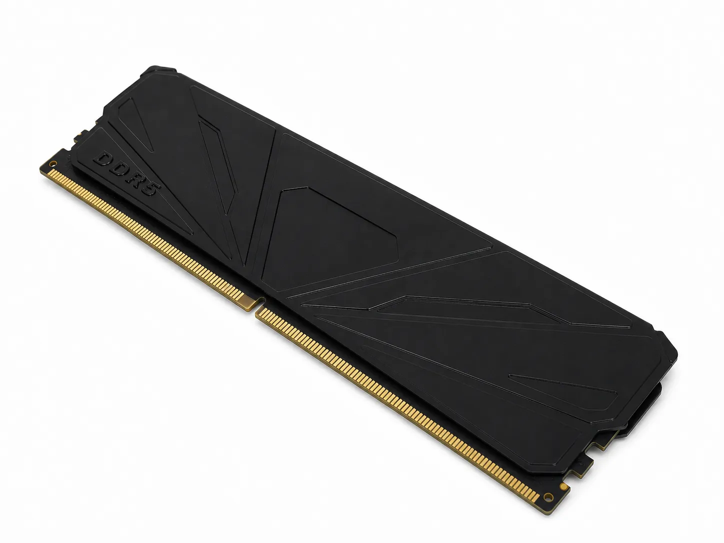
Stamped and formed heat spreaders appear in memory modules, computing hardware, power electronics and cooling assemblies as covers, plates, clips or thin interface parts. Their shapes may look simple, but the combination of thin material, broad visible surfaces, formed details and contact zones can make flatness, marking and handling more important than the outside dimensions suggest.
A metal parts manufacturer can review whether the drawing is practical to blank, stamp, bend, form, finish and inspect. The buyer or system designer still owns heat-source data, interface materials, clamping conditions, airflow and the final thermal acceptance test. Keeping those responsibilities clear produces a more reliable quote and a more useful sample plan.
Short answer: what to include in a heat spreader RFQ
Send a controlled 2D drawing and STEP or STP model, current revision, material and thickness, expected sample and production quantities, critical datums, flatness or profile requirements, contact zones, burr direction, finish, cleanliness, inspection records and packaging scope. Include mating geometry or an assembly view when tabs, clips, holes or bends locate the part.
Describe system thermal targets as buyer validation requirements rather than as an assumed property of the stamped part. A supplier cannot infer junction temperature, interface resistance, clamping pressure or airflow from a plate drawing alone. If conductivity, thermal simulation or a system test is part of acceptance, name the material property source and the test owner.
Separate the part function from system thermal performance
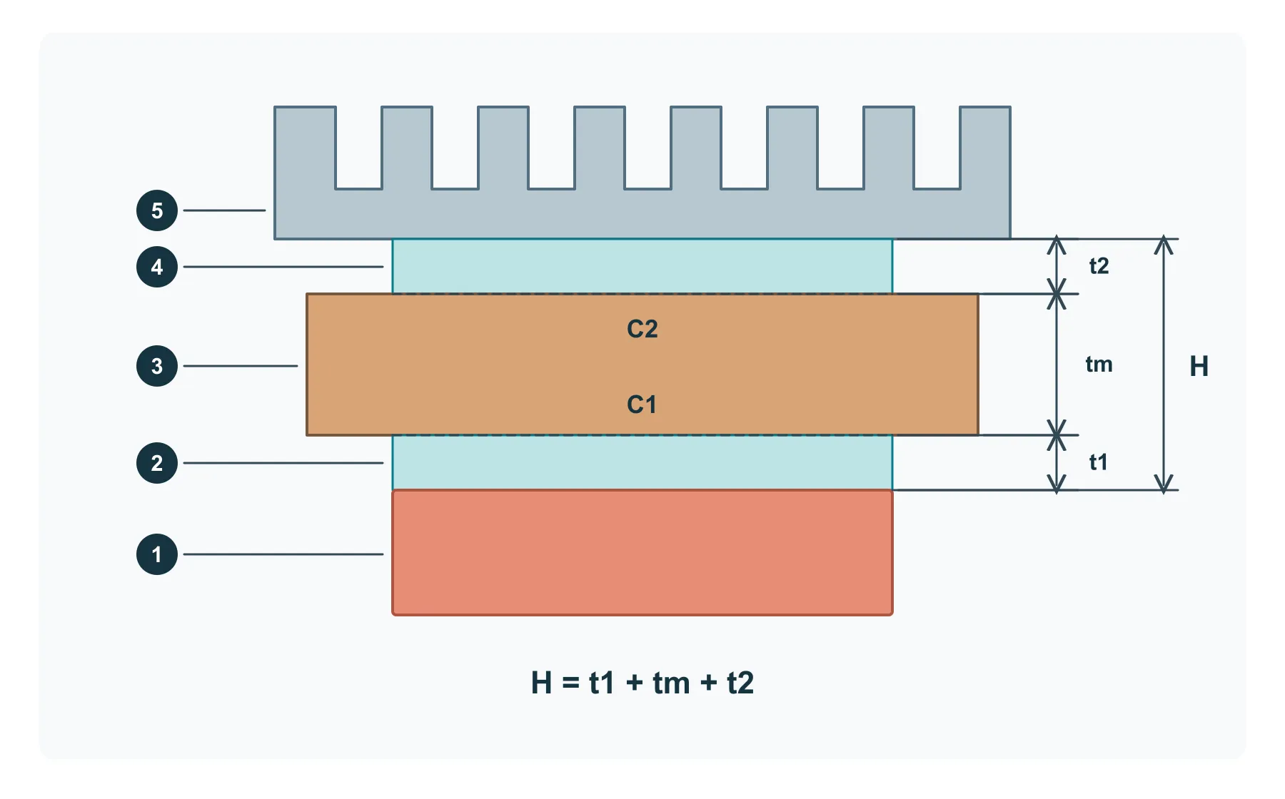
The section shows one possible stack: 1 heat source, 2 lower thermal interface material (TIM), 3 metal shim or spreader, 4 upper TIM and 5 heat sink. Some designs omit a TIM layer or use a different joint; draw the actual assembly rather than copying these layers automatically. TIMs fill interface gaps, but selection depends on gap size and shape, temperature and component stress limits. [2]
C1 and C2 mark the two metal contact faces. Keep their footprints clear of unwanted burrs, embosses and residue. Show the real supports and fastening points as well: clamp force must follow an agreed assembly method and the component and TIM limits, rather than being increased until a gap disappears.
- Identify every layer by part number or material specification and say who supplies and installs it.
- Define installed interface thickness, permissible compression/load and any electrical-insulation requirement from the selected materials and assembly.
- Keep the metal part's drawing checks separate from contact and temperature checks on the assembled stack.
Check the space left for the interface materials
Dimensional example: the controlled assembly provides H = 1.20 ± 0.05 mm, and the finished metal thickness is tm = 0.80 ± 0.03 mm. Nominally, 0.40 mm remains for t1 plus t2. Taking the independent dimensional limits, the minimum is 1.15 minus 0.83 = 0.32 mm; the maximum is 1.25 minus 0.77 = 0.48 mm.
This checks the combined installed interface space, not the required catalog pad thickness. Do not divide it equally between two pads without checking the design. Compare each selected TIM's compression and load data with its assigned gap and the component load limit. The example omits bow, tilt and local gap variation; check those in the actual assembly before approval.
Lock material, temper and thickness before comparing quotes
Aluminum is common where low weight, formability, appearance and thermal conductivity are useful. Copper may be selected where the design needs higher conductivity in a compact section, but it is heavier, more expensive and easier to mark during handling. The specific aluminum or copper grade, temper or hardness affects forming behavior, springback, surface condition and availability, so a generic callout such as aluminum plate is not enough for a controlled quote.
Thickness influences stiffness, mass, forming load, contact behavior and the risk of broad panels distorting. The system designer should select thickness from the mechanical and thermal design, while the manufacturer checks whether the chosen sheet can be cut, stamped, formed and held within the drawing requirements. If alternative grades are acceptable, list them as controlled options and identify who approves a substitution.
- Name the alloy and temper or material hardness when they are functional.
- State nominal thickness and the governing material standard or certificate requirement.
- Separate approved alternatives from supplier suggestions that require written buyer approval.
Design the geometry around contact zones and forming access
Flat plates may include pierced holes, slots, embosses, ribs, coined areas, tabs and edge bends. These features add stiffness or locate the part, but they also redistribute material and can change flatness around a contact region. Closely spaced formed features, short flanges or holes near bends may need different tooling, relief geometry or a revised operation sequence.
Outline where the metal touches a device, TIM or heat sink. Keep nonessential embosses, burrs and markings outside those footprints. Locate holes and formed heights from assembly references; specify the shape of each contact surface separately instead of using a datum to define surface flatness.
- Mark functional contact areas and keep optional features outside them.
- Provide bend directions, inside radii, reliefs and critical flange heights.
- Ask for DFM feedback on distortion risk around embosses, ribs and edge forms.
Specify flatness, profile and surface condition where they matter
Surface flatness applies to the named area without reference to a datum. It controls that surface's shape, not its height or orientation relative to another feature. If C1 and C2 need a particular relationship, specify thickness and the appropriate orientation or profile requirement separately under the drawing's standard. [1]
Separate loose-part inspection from the installed contact check. Record finishing stage, support points and any restraint; clamping a thin plate flat can hide its free-state bow. Use a validated surface measurement covering the contact area, then check assembled gaps with the specified supports and load. Dents, raised edges and residue need their own acceptance criteria even when flatness passes.
Control edges, burr direction and attachment features
Blanking and piercing create an entry side and an exit side, with rollover and burr direction related to the tool orientation. A burr that faces a thermal pad, electrical clearance, cable or assembly operator may create risk even when the overall burr height is small. Mark the preferred burr side on the drawing and identify edges that need deburring, edge breaking or special handling.
Tabs, clips and spring-like features require additional care because their behavior depends on geometry, material temper, grain direction and the forming process. The metal parts supplier can inspect dimensions and sample fit, but the buyer should define the mating component, insertion method and functional cycle or retention check. Avoid assigning an undefined spring force without a corresponding test fixture and acceptance method.
- Show the allowed burr side and edges with special touch or clearance requirements.
- Provide mating-part data for clips, slots, latches and alignment tabs.
- Define any assembly-force or retention check with a fixture, direction and acceptance range.
Coordinate finish, masking, cleanliness and corrosion needs
Anodizing, conversion coating, plating, painting or other treatments may be selected for corrosion resistance, appearance, electrical isolation or assembly needs. A finish can change dimensions at close fits and may alter electrical or thermal contact behavior. Mark areas that must remain conductive, uncoated, masked or protected, and reference the finish specification, color or approved sample where applicable.
Cosmetic heat spreaders require careful movement through stamping, forming, finishing and packing. Protective film may help on some sheet conditions but can conflict with forming or later treatment, so its use should be planned rather than assumed. State whether parts must be free of visible oil, fingerprints, particles or adhesive residue and how that condition will be evaluated.
- Identify visible faces, contact zones, masked areas and permitted rack or contact marks.
- Define finish standard, color or appearance reference and any required compliance records.
- List cleaning, protective-film removal and final handling requirements in the quote scope.
Choose stamping or flexible fabrication from volume and revision risk
A simple thermal shim or early prototype may be laser cut, punched or made with simple tooling when the design is still changing. Repeated formed features, clips, embossed details or higher stable demand may justify production stamping tooling. The lowest-risk path is not always the route with the lowest first sample price; it is the route that answers the current engineering question without creating a false expectation about production behavior.
Give realistic sample, pilot, batch and annual quantities for each variant. Ask the supplier to separate one-time tooling or programming from per-part and per-batch costs. If a fabricated sample will not reproduce production material condition, edge quality, forming strain or flatness, document that limitation and plan a production-intent trial before release.
Approve samples with part-level and assembly-level checks
First samples should confirm material, thickness, critical dimensions, contact-zone flatness or profile, burr direction, finish coverage, appearance, cleanliness and packaging. Assembly checks can then confirm that holes, clips, pads and mating surfaces align without interference. Use a controlled drawing revision and record any approved deviation or DFM change before production files and tooling are frozen.
Thermal validation comes after the mechanical basis is known. The buyer should test the part in the intended assembly with the specified interface material, fasteners or clamping condition and operating environment. If the system result leads to a geometry or material change, release a new revision and identify whether new samples, tooling changes or repeat inspection records are required.
- Separate dimensional and appearance approval from system thermal testing.
- Record the sample material, finish, tooling route and assembly configuration.
- Require a new controlled revision before changed samples enter pilot or repeat production.
Put the drawing and assembly notes in one RFQ
Send one consistent revision so the quote, sample inspection and assembly trial refer to the same part. The contact sketch and stack notes can accompany an unfinished drawing; list unresolved items for discussion.
- Part definition: drawing/model, material condition, finished thickness, contact areas, geometry and finish.
- Assembly definition: layer list, gap limits, fastening/support conditions and responsibility for TIMs or hardware.
- Delivery and approval: quantities, inspection and packaging, sample purpose and the owner of the assembled thermal test.
| RFQ decision | Why it changes manufacturing risk | What the buyer should define |
|---|---|---|
| Part function | A cover, contact plate, clip and shim have different critical features. | Assembly role, mating components and which results are system-level tests. |
| Material and temper | Alloy and condition affect forming, springback, marking, flatness and availability. | Exact grade, temper or hardness, thickness, alternatives and certification. |
| Contact zones | Embosses, burrs, coating or distortion can affect the intended interface. | Contact footprints; surface flatness without a datum reference; separate assembly relationships, surface condition and inspection state |
| Formed geometry | Bends, clips, ribs and embosses affect access, operation sequence and distortion. | Bend direction, radii, reliefs, critical heights and mating geometry. |
| Edges and burrs | The wrong burr side can affect pads, clearance, assembly or handling. | Preferred burr direction, deburred edges and inspection basis. |
| Finish and masking | Coating can change appearance, electrical contact, dimensions and cleanliness. | Finish specification, visible faces, masked areas, permitted marks and records. |
| Samples and validation | A flexible prototype may not reproduce the production stamping route. | Sample purpose, production-intent stage, assembly checks and thermal test owner. |
| Packaging | Broad thin surfaces can be scratched, rubbed, contaminated or bent after inspection. | Separators, orientation, pack quantity, labels, cleanliness and transport trial. |
| Repeat production | Uncontrolled substitutions or revisions can change form, fit and delivered condition. | Revision process, retained inspection basis, approved packaging and change notice. |