A steel enclosure has a thick coating outside but bare areas inside a flange. Another batch of brackets comes out of the oven with uniform color, yet the coating chips around the holes during fastening. Both are powder-coated parts, but the first problem may concern where the powder reaches, while the second also requires checks of the interface, cure, and assembly. Identify the stage at which the problem arises before deciding what to adjust.
Photo case: why is powder coating rougher near a flange?
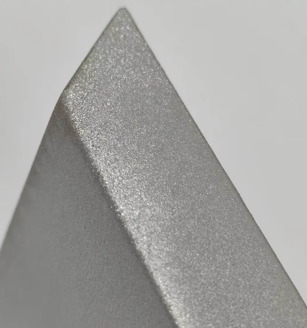
The powder-coated part in the photograph has a visibly coarser texture near the flange than on the adjacent large face. Record the observation as localized texture coarsening before naming a cause. For a specified smooth finish, investigate orange peel or poor flow. For a textured powder, compare texture consistency with the approved sample. Different lighting angles affect the two faces, so brightness cannot establish thickness or make the adjacent face an accepted reference.
When roughness follows the flange, check local deposition and overlapping spray passes first. Spraying the large face and the flange can cover the same band twice; pausing at a turn or repeated touch-up also adds powder. Preferential deposition at exposed edges can amplify the difference. A heavy deposit may produce a coarser, frame-like appearance, but a location-based thickness map is needed to confirm it.[11]
Also investigate back-ionization. Excess charge in the deposited layer can cause local discharges that disturb the powder and leave fine depressions or roughness. Close gun distance, excessive charging, poor grounding and high film build can contribute. Observe the uncured layer for star-like disturbances, small pits or powder rejection, and record actual spray current rather than relying only on the baked appearance.[4]
The photograph establishes the location of the coarse texture; it does not prove back-ionization, through-film pinholes or undercure. Substrate, powder product, film thickness and workpiece-temperature records are still needed. If an uncoated part already has a rough band on the outside of the bend, investigate forming and surface preparation as well.
| Check first | How to distinguish the cause | Corrective trial and verification |
|---|---|---|
| Local thickness and overlapping passes | Map several readings across the rough band, a flat flange area and the large face; compare spray paths and touch-up locations. | Reduce dwell and repeated coverage, targeting the powder product’s specified thickness; verify that inner areas and edges retain required coverage. |
| Excess charging and grounding | Observe the uncured layer, inspect hook contact and actual current, and compare areas close to the gun. | Restore reliable grounding, then separately test current limiting, voltage or distance within equipment guidance; avoid changing every setting together. |
| Substrate condition at the bend | Inspect uncoated parts from the same batch at the outer bend, tool-contact and grinding locations. | Control forming and preparation consistency; extra powder is not a reliable remedy for every substrate irregularity. |
| Powder and reclaim condition | At comparable film build, compare a flat panel with the same formed geometry; record storage, agglomeration and virgin/reclaim use. | Follow supplier guidance for sieving, storage and reclaim. For metallic effects, also confirm reclaim suitability and appearance consistency. |
| Actual workpiece heating | Compare warm-up and effective hold time with the powder TDS; retain load and hanging conditions. | Adjust only within the approved cure window. Local roughness alone does not justify a hotter oven, and appearance alone does not establish cure. |
Use an instrument and probe suited to the substrate and geometry. Readings beside sharp edges, curves or rough surfaces can be affected; verify the method and instrument requirements. An acceptable overall average does not establish acceptable local thickness at the flange.[6] Both high and low film build can impair flow, so measure before deciding to reduce output.[12]
Verify the correction on repeat parts, not just one improved sample
Keep an original-process sample as a control. With the same geometry, powder batch and comparable pretreatment and cure, first change the flange overlap or touch-up practice and check texture together with thickness. If the issue remains, separately test current limiting or gun distance and retain the actual settings.
Compare the same locations under the same lighting and viewing angle. Keep individual thickness readings, photographs before and after baking, and assembly results. If lower deposition improves appearance, also confirm that inner flanges, openings and other specified areas have not become thin or bare. Complete the specified coverage, cure, adhesion and functional checks against the drawing and approved sample.
A useful supplier request is: “Texture is locally coarser near the flange. Please compare film thickness there with the large face, check overlapping passes, touch-up and excessive charging, and provide same-geometry photographs and measurements before and after the trial.” This gives a verifiable investigation rather than an unsupported conclusion that the powder or oven is at fault.
Choose the powder system before discussing application conditions
“Electrostatic powder spraying” describes how charged dry powder is delivered to a workpiece. It does not define the resin, intended use, or cure requirements. Thermosetting powders undergo irreversible crosslinking when heated. Thermoplastic powders mainly form a film by melting and cooling, so they are not assessed using the same chemical-cure logic. This article focuses on electrostatic application of thermosetting powders commonly used on metal enclosures and brackets.[1]
Names such as epoxy, polyester, and epoxy-polyester hybrid help identify candidate materials but do not directly determine service life. Common epoxy systems need to be assessed for chalking and appearance changes in locations exposed to prolonged sunlight. Where outdoor color and gloss retention matter, suitable weather-resistant polyester products and other options can be discussed. The specific formulation, pigments, weatherability grade, and complete coating system still need to be checked; “polyester” does not establish that every outdoor requirement has been met.[1][2]
When developing the process, obtain the actual product's technical data sheet (TDS). Confirm suitable substrates, pretreatment, recommended film thickness, appearance, cure window, and compatibility with primers or existing coatings. The same black color code can describe products with different gloss, texture, and heating requirements. A color chart cannot replace the product identification.
If you are still comparing processes, start with the comparison of powder coating, electroplating, and anodizing. This article explains how to produce an acceptable coating once a powder has been chosen.
Plan the process steps and inspection locations together

A coating defect may have its origin before the spray gun starts working. Process records should identify the part batch, powder batch, hanging position, and time the problem was found, rather than recording only the last gun pressure or oven temperature.
For an enclosure with flanges, welded nuts, and grounding studs, first mark the large appearance surfaces, inside flanges, hole openings, areas beside welds, hanging points, and electrical-contact surfaces on the drawing. Trial-coating photographs, thickness records, and assembly problems can then refer to the same locations.
The process window depends on the powder, pretreatment, and equipment. There are no universal gun-distance, voltage, film-thickness, or oven-temperature and time settings suitable for every part. Record the actual conditions and verify them on representative samples.
Pretreatment addresses what lies beneath the coating
Powder covers the substrate but does not automatically remove stamping oil, rust, mill scale, welding slag, or cleaning residues. Pretreatment needs to make the actual surface suitable for the selected system and, where required, form a compatible conversion layer before rinsing and drying. Steel, galvanized steel, and aluminum have different surface conditions. Their ability to conduct electricity does not justify using exactly the same pretreatment route.[2]
For sheet-metal parts, inspect three types of location in addition to the large flat surfaces:
- Cut edges and weld areas. Loose oxides, burrs, and weld spatter can remain beneath the coating. In particular, assess the edge oxide formed by oxygen-assisted laser cutting. This does not mean that all laser-cut edges require the same grinding method.[2]
- Flanges, weld seams, and liquid traps. A dry flat surface does not prove that narrow gaps contain no water or treatment solution. Check the hanging orientation, drainage paths, and drying together.[2][5]
- Areas handled after cleaning. Fingerprints, anti-spatter agents, oil and water in compressed air, and contamination from nearby operations may recontaminate a cleaned surface.[3][10]
For grinding or blasting, define what is to be removed and the surface condition permitted afterward, then remove the residues. Increasing roughness does not replace degreasing. Excessive roughness may also show through in the appearance or make complete local coverage more difficult.[2]
The drying oven and curing oven have different tasks: the former removes water from pretreatment, while the latter forms the powder film. Sending wet parts into the spray booth and expecting the final bake to resolve the problem may leave vapor and residues to emerge while the film is forming.[2][5]
Electrostatic deposition: why the outside can be thick while recesses remain thin
After charging in the spray gun, powder reaches a grounded workpiece through the combined action of airflow and the electric field. The contact path from hooks and racks to the workpiece must be reliable. Old coating, oil, or loose contact can affect deposition. A conductive metal substrate does not prove that the grounding path remains effective once the part is hung.[3]
Electrostatic attraction temporarily retains powder before it melts. This differs from the cured coating's resistance to separation from its underlying surface. If powder falls off before entering the oven, first check grounding, powder feed, airflow, and handling vibration. If the formed coating peels, also investigate the failure interface and cure. Calling both problems “poor adhesion” obscures the different stages.[2][3]
Deep flanges, slot openings, and cavities often show a Faraday-cage effect: powder deposits more readily on the outer edges, while effective deposition deeper inside is weaker. Spraying longer may continue building powder near the opening without increasing the inner deposit at the same rate. Evaluate hanging arrangements, spray angles, nozzles, powder-feed airflow, and voltage and current control together in relation to the actual geometry.[3][10]
First check whether the powder has a suitable path to the required area, then adjust the application conditions. Excessive airflow may blow powder out of an internal corner; insufficient airflow may fail to deliver it there. Test within the equipment's permitted operating range and compare thickness in the recess, at the outer edge, and on the large surfaces, rather than pursuing a single setting.[3]
Back-ionization is a different problem. As the powder layer thickens and accumulates charge, the local electric field may cause small discharges that disturb the powder layer and ultimately produce dimples or a rough appearance. Excessive charging, unsuitable gun distance, poor grounding, and an overly thick powder layer may contribute. This differs from a recess that is difficult to coat from the start. A photograph of a single depression cannot rule out contamination either.[4]
How melting, flow, and crosslinking form the finished coating
As thermosetting powder heats, its particles soften, melt, and join into a continuous film. While the melt can still flow, it reduces surface unevenness. Crosslinking progressively restricts that flow and ultimately produces a cured film. These processes overlap; they should not be understood as three independent switches.[1][5]
Appearance depends on whether the time available for flow suits the initial powder layer. Aged or partially reacted powder, locally excessive or insufficient thickness, and unsuitable heating can all change the final texture. Raising the temperature may improve one condition while also shortening the opportunity for flow or causing discoloration. First confirm the powder product, storage condition, film thickness, and temperature profile.[2][10]
Textured powders may deliberately create an uneven surface. Before classifying orange peel as a defect, use an approved sample to establish whether the required finish is smooth, finely textured, or coarsely textured. Compare under the agreed lighting; not every uneven surface is the same defect.
Check workpiece temperature for cure, not just oven temperature
When the TDS specifies cure by workpiece temperature, the effective time after the part reaches the required temperature is what matters. Oven air heats first, while the workpiece may still be warming. Thick reinforcement plates, thin covers, and different hanging positions may also experience different heating profiles.[5]
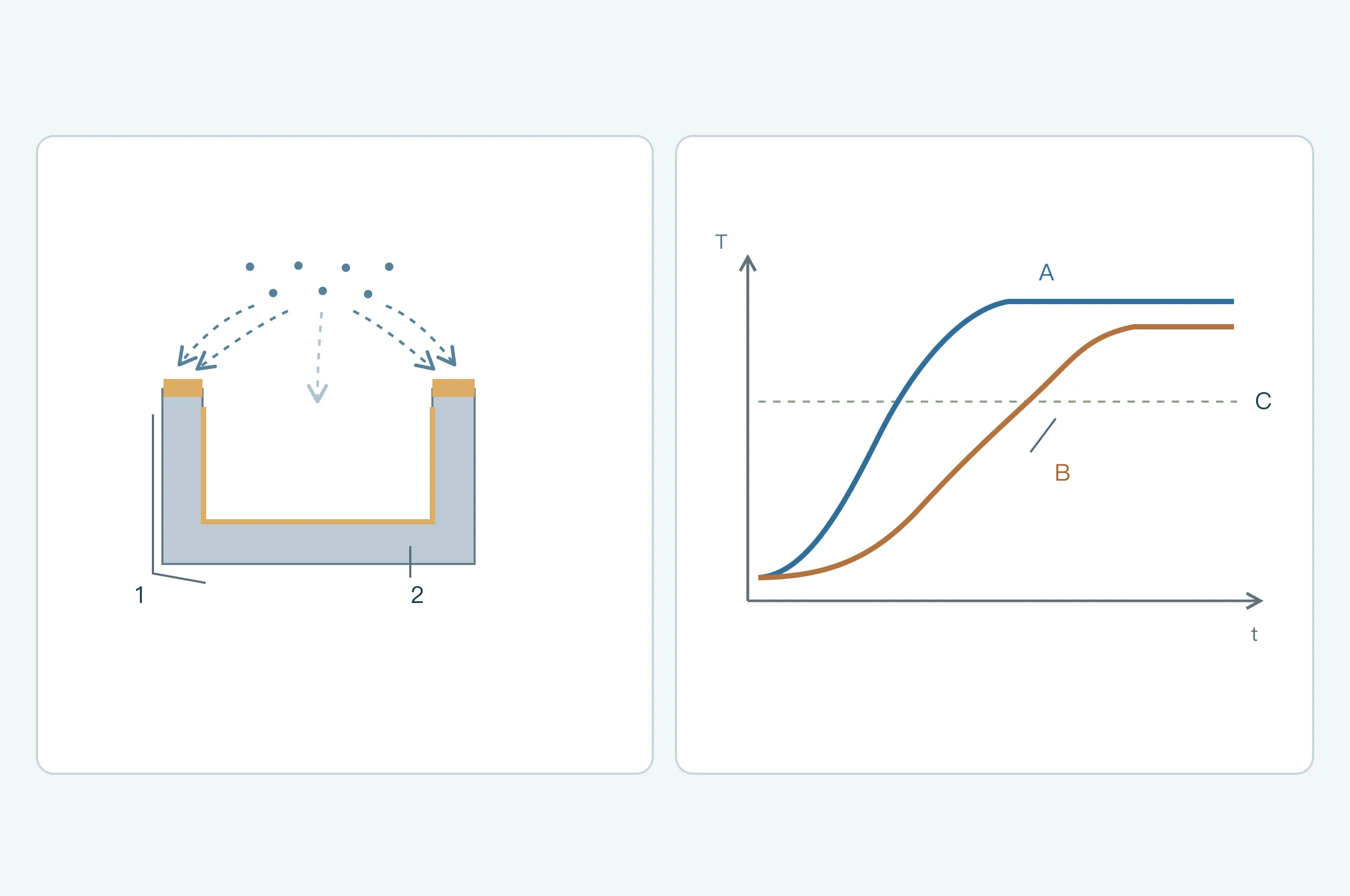
Temperature records should cover representative thin and thick areas and slower-heating locations, and retain the loading, line-speed, or oven-time arrangements. The two curves in Figure 2 simply illustrate possible differences in thermal response. Actual acceptance requires comparison with the product's permitted temperature and time combinations. The schematic horizontal line is not a universal curing temperature.
A smooth appearance does not prove that crosslinking has reached the level required in service. Excessive heating may also cause color or mechanical performance to deviate from the requirements. If primer and topcoat receive separate bakes, or rework involves another bake, check each layer's cumulative thermal history and the heat tolerance of the substrate and components.[5]
An appropriate solvent-rub test assesses solvent resistance under specified conditions. Reaching a given level does not by itself prove complete cure. The solvent, number of rubs, and acceptance criteria depend on the product and agreed method; a casual wipe cannot represent the entire cure-acceptance process.[8]
Distinguish orange peel, craters, and pinholes
Use defect names to describe observations before proposing causes. Record whether the defect first appeared in the spray booth, on oven entry, or after cooling, and which face, substrate, and hanging position are affected. This provides more useful evidence than immediately changing the powder for the whole batch.
| Appearance and distribution | Possible mechanisms | What to verify first |
|---|---|---|
| Continuous orange peel where a smooth finish is required | Mismatch between the initial powder layer, flow time, and crosslinking; substrate texture showing through | Check the approved appearance, local thickness, storage condition, and actual heating profile; compare controlled specimens coated with the same powder |
| Craters, fisheyes, or depressions | Oil, water, silicone, or contamination by a different powder; back-ionization may also be involved | Compare the powder layer in the booth with the baked finish; check contamination sources, color-change cleaning, and grounding; retain a clean control specimen |
| Pinholes or small bubble pits appearing after oven entry | Outgassing from the substrate or residues; damp powder; volatiles produced by the reaction in some systems | Compare substrate batches, drying, powder condition, and local thickness; examine a cross-section if necessary |
| Bare areas in recesses while powder builds up on outer edges | Interaction between delivery path, electric field, airflow, and geometry | Compare hanging or spraying arrangements on the same part; record inner and outer locations rather than measuring only large surfaces |
| Locally excessive thickness, runs, or buildup along the lower edge | Overlapping spray paths and excessive powder delivery; flow during melting | Compare the corresponding powder layer, spray paths, and hanging orientation; check the heating profile and final fit |
| Color variation, mottling, or uneven gloss | Hiding power and film thickness, heating, batches, and changes in the composition of reclaimed powder | Use fixed lighting and viewing angles; check powder batches, actual temperature profiles, and virgin/reclaim arrangements; for effect powders, also check application consistency |
The table gives investigation directions, rather than a one-to-one mapping of observations to causes.[2][3][4][5][10]
Why pinholes can occur without a liquid solvent
Dry powder has no liquid carrier like wet paint, but gases may still need to escape during heating. They may originate in the substrate, pretreatment residues, underlying coatings, or the powder itself. For example, the curing systems in some polyester powders release water during reaction. The timing of gas release, film thickness, and the period during which the surface can still flow together determine whether holes remain.[2][5]
Investigate outgassing from castings or galvanized parts, residual water in flanges, and moisture in powder separately. Preheating to remove gas or using a suitable outgassing-tolerant powder may be options, but temperature, time, and subsequent coating arrangements need to be established by trials. Also check changes to the metal coating, substrate, and components. An outgassing-tolerant product cannot guarantee the elimination of every severe outgassing problem.[5]
Record reclaimed powder as a process variable
Recovering overspray does not mean the recovered powder can be added without conditions. Reclaiming may change the particle-size distribution, and leftover powder from color changes or other contamination may enter the system. Effect powders also require consideration of possible separation between metallic pigments and the base powder, which may affect appearance.[2]
For the actual product, confirm whether reclaim is allowed and how replenishment can be kept consistent. Record the use of virgin and reclaimed powder. Do not apply one guide's recommended ratio to every powder, or mix in an unverified same-color powder to correct color variation.
Use controlled comparisons to find the cause, then verify it on actual parts
Each comparison should answer one question while retaining the original conditions. For example, to investigate whether recess coverage depends on hanging orientation, compare hanging arrangements using the same part, the same powder batch, and comparable other conditions. When checking whether inner coverage improves, also check whether outer edges become thicker or thickness variation increases.
If undercure is suspected, first obtain the actual temperature profile, then compare heating arrangements within the product's permitted range and reassess mechanical performance and appearance. If pinholes may come from substrate outgassing, compare substrate preparation routes with the same powder and record the thermal response at each location. Flat panels and complex parts may heat differently; do not mistakenly attribute that difference to the powder.
Retain unrepaired defective parts, acceptable parts, batch details, and process records for each trial. Changing powder, gun paths, thickness, and oven temperature simultaneously makes it difficult to identify the effective change, even if appearance improves. Confirm the diagnosis on repeat samples and actual part geometry.
Acceptance needs to cover appearance, coverage, and assembly
Finished-part acceptance must at least define inspection locations, methods, and criteria. A single flat color panel cannot establish film thickness inside an enclosure flange, fit at a welded nut, or an electrical path through a grounding stud.
| What to confirm | Inspection arrangements | Records to retain |
|---|---|---|
| Color, gloss, and texture | Approved sample or color panel; agreed lighting, viewing distance, direction, and visible surfaces | Powder product, batch, allowable appearance variation, and defect locations |
| Film thickness and complete coverage | Choose a thickness-measurement method for the substrate and geometry; dismantle or examine cross-sections in deep areas where necessary | Location map, individual readings, instrument checks, and local criteria; for multiple layers, state total thickness or layer-specific results |
| Cure and mechanical performance | Compare the temperature profile with the TDS and use adhesion, bend, or impact checks required by the application | Thermal history, test locations, method and edition, specimen condition, and the location of separation |
| Fit and electrical contact | Finished-hole, thread, location, sealing, and final-assembly electrical checks | Areas to remain uncoated, masking method, dimensions after treatment, fastening condition, and results |
| Environmental protection | Choose tests for the actual moisture, cleaning, sunlight, or corrosive exposure | Complete coating system, specimen condition, exposure conditions, and failure criteria |
Confirm calibration, verification, and adjustment for magnetic or eddy-current thickness measurement according to the instrument and applicable method. Edges, curved surfaces, small holes, and rough surfaces may affect readings. A single reading or overall average cannot replace results at critical locations.[6]
Powder coatings occupy mating space. Where coating actually forms on both sides of a hole, the sum of the cured film thicknesses on the two sides can estimate the reduction in hole diameter. That geometric relationship alone cannot determine thread acceptance. Check the finished part using the required gauges or assembly conditions. Link holes, sealing surfaces, and grounding locations that need masking between the drawing and the process.
An ordinary organic powder film should not be treated as a reliable electrical-contact surface. After preserving a contact area or specifying a local treatment, verify the electrical path under the final fastening conditions and consider protection of exposed areas. Good rack grounding during spraying does not establish acceptable grounding in the finished assembly.[3][5]
Choose an applicable adhesion-test method. ASTM D3359 cut-and-tape ratings do not provide an absolute force for interface failure, and the method is not technically equivalent to ISO 2409. Failure in a multilayer system may occur between layers; the report should identify where separation actually occurred.[7]
Assess corrosion resistance and weatherability separately for the application. Salt spray provides comparisons under a controlled environment. ASTM B117 does not automatically define a specific product's exposure duration or acceptance criteria, and an isolated salt-spray result cannot be converted into years outdoors.[9]
Before rework, determine which layers can remain
Local appearance repair, touch-up painting, recoating with powder, and stripping followed by recoating solve different problems. Whether the existing film can remain depends on defect depth, interface condition, compatibility, and service requirements. Covering a depression does not show that contamination or pores beneath it have been eliminated.
Applying powder again over a cured film is also affected by the existing layer's insulating and electrostatic behavior, so bare-part settings cannot simply be reused.[2] For recoating, confirm cleaning, any necessary surface preparation, cumulative thickness, and the additional bake. For local repairs, reassess color, protection, and the relevant functions.
If there is widespread peeling, intercoat failure, or underfilm corrosion, first define the removal scope, then assess whether the substrate, metal coating, and dimensions remain usable. See the metal baked-paint peeling and adhesion guide for a fuller investigation. Retain the original batch, number of rework cycles, and renewed acceptance results for reworked parts.
Start with the application and drawing to define requirements
Send a drawing, sketch, or photograph with the material, application, expected quantity, and locations of appearance surfaces, recesses, mating holes, threads, seals, and electrical contacts. If there is an existing defect, include the stage where it was found and photographs taken before repair. Mark undecided powder, thickness, or test requirements as “to be confirmed” so that samples, acceptance, and quotations can be discussed around the actual part.
- [1] PPG Coatings Services — Powder Coating Process Specifics
- [2] TIGER Coatings — Tips & Tricks for Powder Coating: Troubleshooting Guide (01-2022)
- [3] Nordson — Powder Coating System Troubleshooting Guide, PWL-14-3292 (2014)
- [4] Powder Coated Tough — Ask the Experts (September–October 2024), republished by Gema
- [5] PPG Powder Coatings — FAQ: cure curves, cure checks, storage and outgassing
- [6] ASTM D7091-22 — Nondestructive Measurement of Dry Film Thickness
- [7] ASTM D3359-23 — Rating Adhesion by Tape Test
- [8] ASTM D5402-19(2024) — Solvent Resistance of Organic Coatings Using Solvent Rubs
- [9] ASTM B117-26a — Operating Salt Spray (Fog) Apparatus
- [10] IFS Coatings — Powder Coating Troubleshooting Guide
- [11] IFS Coatings — Appearance Issues in Powder Coating: Picture Framing
- [12] Axalta — Problems on the coated object: Levelling (orange peel)