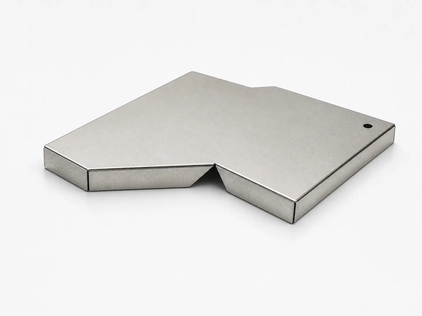
A flat-looking roof does not show whether a shielding can will sit evenly on its PCB. The soldering edge may bow, one tab may sit higher than the others, or a burr may hold the part away from the board. Inspection should follow those functional surfaces.
You do not need to choose a scanner or write a measurement procedure before requesting a quote. A drawing or photo showing where the shield touches the board, together with a description such as ‘this corner lifts’ or ‘the lid will not seat’, gives the engineering review a useful starting point.
Which part of the shielding can needs to be flat?
The surface to control is the one that performs the function: a soldering flange, separated solder tabs, a contact rim or a lid seat. A roof-flatness result does not establish that the soldering interface is acceptable. Mark the relevant areas on a drawing or photo before deciding what to measure.
Surface flatness controls a surface between two parallel planes separated by the specified tolerance. It is a form tolerance and does not reference a datum. A support fixture or a software reference plane may still be needed to make a measurement; that does not turn either into a datum required by the flatness tolerance. [1]
- Continuous flange: evaluate the designated soldering surface, with the drawing defining whether the whole flange is controlled together.
- Separated tabs: clarify which tabs must share a common tolerance zone. Each tab can be individually flat while one tab sits above the others; separate flatness checks do not establish their coplanarity.
- Height or orientation relative to another feature: use the drawing's relevant dimensional or geometric requirement and datum references. Do not label every height difference ‘flatness’.
Should the shield be measured loose or held in a fixture?
Measure a shielding can in the condition named in its acceptance requirement. A loose part, a restrained part and a soldered assembly can have different shapes. Pressing a lifted corner down may hide the incoming-part problem, while a defined assembly restraint may be appropriate when the requirement concerns the installed condition. [2]
Agree the support locations, orientation and any holding force. For a free-state check, avoid an extra load that flattens the part; a vacuum nest also needs review because it can pull a thin roof into shape. A setup photograph makes comparisons easier than a note saying only ‘measured on a fixture’.
- Record the inspection stage: after forming, after finishing, after transport or after soldering. Compare results from the same stage when judging supplier agreement.
- Inspect the reference surface and part for debris. A trapped particle or burr can make the shield rock; record and investigate it before treating the result as general warpage.
- Keep part and PCB checks separate when diagnosing assembly gaps. Board warpage, solder paste and placement conditions can also affect the assembled joint.
How can a feeler gauge check a shield that rocks or lifts?
A feeler gauge is useful for checking an accessible gap between a supported shielding can and a verified reference surface. The blade shows whether a gap admits a known thickness at a named location. This is a practical seating-gap check; it is not automatically a full measurement of the surface's flatness.
Start with a clean reference surface and the agreed support condition. Locate the lift without pressing the roof, then bring the blade in parallel to the gap with light, consistent handling. If insertion moves or bends the shield, the reading is unreliable and a different setup or method is needed.
- Coverage: check the specified corners, long edges and tabs. Checking four corners alone can miss a bow between them.
- Record: identify each position and the blade that enters without moving the part; where useful, record the next thicker blade that does not enter. Do not report more precision than the blade increments support.
- Escalation: use a suitable height-measurement method when the gap is inaccessible, results depend strongly on handling, or the drawing requires a geometric result beyond the validated gauge check.
When do optical sensors and 3D scanning add useful information?
A 3D laser line scan is useful when inspection needs heights across a flange or multiple tabs, including distortion between manual check points. The sensor captures successive profiles as the part or sensor moves and combines them into a height map. Software then evaluates the features selected for the drawing requirement. [3]
Fixed optical sensing can check selected positions quickly when the part is presented consistently. The actual setup matters: a calibrated displacement sensor can return heights, while a beam or threshold arrangement may provide only a pass/fail signal. Neither arrangement automatically inspects the spaces between its measurement points.
- Check coverage on narrow tabs and edges, including areas hidden from the laser or camera by a wall or fixture. A missing reading must not silently count as a pass.
- Validate the actual material and finish. Reflections, motion, point spacing and the sensor's working range can change the usable data.
- Ask which points the software removes and why. Filtering that suppresses reflection noise must not erase a real bent tab or a functional edge defect.
Reading a height report: a numerical example
Suppose four sampled points have heights of 0.02, 0.03, 0.04 and 0.09 mm relative to the same fixed reference plane. Their sampled height range is 0.09 − 0.02 = 0.07 mm. This identifies a difference among those points; it does not establish the flatness of the entire flange.
The reference plane may include part tilt, and four points may miss a raised section between them. A flatness evaluation must use the relevant surface data and the evaluation method required by the drawing specification. For tab coplanarity, evaluate the specified tabs together; fitting each tab separately can conceal their relative height difference.
Which appearance defects matter for a PCB shielding can?
Appearance inspection should distinguish damage that affects assembly or contact from marks that are only cosmetic. Ordinary 2D vision using CCD or CMOS cameras can check visible outlines, missing features and surface changes. Height, burr size, coating thickness or electrical contact quality need their own suitable checks when they are acceptance requirements.
Use annotated photographs or approved samples to show acceptable and unacceptable conditions in each area. For visual comparison, agree lighting, viewing direction, distance and magnification. A darker patch in a photograph alone does not identify whether the cause is contamination, finish variation or a lighting reflection.
- At the PCB and soldering edge: look for bent tabs, loose metal particles, burrs that interfere with seating, and contamination in the joining area. Identify the affected location and assess the functional consequence.
- At the lid and contact rim: check dents, distorted clips and damage that prevents seating or engagement. Use a mating-fit check if the function cannot be judged from an image.
- On cosmetic surfaces: define where scratches or tool marks are acceptable and what requires review. A mark on a hidden wall and the same mark on a visible cover may have different acceptance rules.
- For finish concerns: separate visible discoloration or damage from coating thickness, adhesion and solderability requirements. A vision pass does not establish those properties.
How do you know the inspection method is dependable?
A dependable inspection method gives consistent results on representative parts and distinguishes acceptable parts from relevant defects. Verify the whole setup: instrument, support, loading, software and operator. Sensor resolution describes a measurement increment; it does not by itself establish the uncertainty of the final result. NIST's gauge-study guidance treats variability and bias as separate issues to investigate. [4]
- Use representative samples: normal production variation, known bent features, finish variation and parts close to the acceptance boundary. Establish their reference status with an agreed, suitable method.
- Repeat the complete loading cycle: remove and replace parts between readings. Include relevant operators, days or fixture changeovers; rescanning one untouched part leaves handling variation untested.
- Check numeric agreement: review repeated results and differences from the reference method. A gauge R&R study helps assess variation, while calibration, bias and other uncertainty contributions also need attention.
- For pass/fail sorting, report both mistakes separately: false rejects are acceptable parts rejected divided by acceptable parts tested; escapes are defective parts accepted divided by defective parts tested. State counts and defect types, not only an overall ‘accuracy’ percentage.
- Trial the complete cycle: loading, inspection, calculation, sorting and packing. Verify where rejected and unreadable parts go, and recheck the method after a material, fixture or software change.
What should happen when buyer and supplier results disagree?
When a shielding can passes one inspection and fails another, compare the measurement conditions before changing the tolerance or rejecting the lot. Check that both teams measured the same feature, drawing revision and process stage. Then compare supports, restraint, point coverage and calculation settings using the same retained samples.
Keep borderline or unreadable parts separate while the agreed review method resolves them. Do not choose whichever repeat reading happens to pass. The inspection report should connect each result to a part or lot, the controlled feature, limit, method, setup and any review decision; a single ‘OK’ entry is insufficient to explain a disagreement.
- If the gap changes after reloading, investigate seating, debris, support and handling first.
- If manual and optical checks disagree, confirm whether both are checking the same seating gap or geometric characteristic, then compare coverage and raw data.
- If the problem appears only after soldering or shipment, compare samples before and after that stage and review the assembly or packaging conditions.
| Method | Useful question | Result | What to verify |
|---|---|---|---|
| Reference surface and feeler gauge | Is there an accessible seating gap at a specified location? | Blade-based gap check | Handling force, supports and coverage; no automatic full-surface flatness result |
| Fixed optical sensing | Are selected edges or heights within the agreed limits? | Point heights or pass/fail, depending on the sensor | Sensor principle, stable positioning and distortion between check points |
| 3D laser line scan | How do the selected flange or tab surfaces vary in height? | Height map and defined geometric evaluation | Reflectivity, blind spots, point spacing, calibration and evaluation settings |
| 2D vision with CCD or CMOS cameras | Are visible features and surface conditions acceptable? | Images, feature measurements and defect classification | Lighting, approved defect examples and required views; height needs additional measurement |
| Combined geometry and vision inspection | Does each part pass both geometric and visible-defect checks? | Linked results and sorting decision | Part tracking, changeover checks, unreadable-part handling and reject separation |