Writing only “poor appearance” rarely tells an electroplater what to do next. Similar dark patches may result from incomplete coverage, surface residues or post-treatment; small spots may be depressions or raised particles. Describe the observation first, then use its location and process records to narrow the investigation.[1]
Confirm which layers are actually present
“Electroplating” does not specify a single finished surface. Zinc may be followed by passivation and a sealer; decorative nickel/chromium may include an undercoat, nickel and a very thin chromium layer. Tin-plated parts may also need solderability or electrical contact performance. The visible outer color does not establish the condition of every layer underneath.
Before investigating, agree on at least four items: substrate grade and condition; the sequence of coatings and post-treatments; specified thicknesses and measurement locations; and whether the defect was found after plating, assembly or storage. Without knowing which layer is missing, decisions about replating or rework lack a sound basis.
This guide covers observation and investigation of metal electroplated parts. Nickel, zinc, tin and decorative nickel/chromium use different chemistries and operating windows; specific corrections must follow the relevant process. E-coat, powder coating and PVD form films differently and need their own troubleshooting methods.
Distinguish the five defects first
| Defect | Describe the observation | Priority checks | Useful evidence |
|---|---|---|---|
| Peeling or blistering | An intact raised blister or detached flakes; exposed substrate or another metal layer | Separation interface, cleaning/activation, transfers between layers and later loading | Unreworked defective parts, cross sections or fracture surfaces, suitable adhesion tests |
| Pits or roughness | Depressions or raised spots; whether they existed before plating | Substrate surface, bubbles, particles, wetting and filtration | Same-location before/after comparison, magnified observation, defective and sound parts |
| Burnt deposits | Whether rough or dark deposits cluster at tips, outer edges or anode-facing surfaces | Local current density, loading, bath condition and temperature | Rack-position map, current records, appearance and thickness by location |
| Missing coverage or locally thin plating | No coverage at all or a deposit that is present but too thin | Surface activity, electrical contacts, shielding, trapped gas and recess coverage | Thickness at specified points, contact inspection, controls with changed rack positions |
| Color variation | Overall color shift, local bands or water-stain patterns | Coating system, roughness, post-treatment and viewing conditions | Comparison under the same light and orientation, staged samples, relevant thickness/composition checks |
These are starting points for an investigation. One defect may have several causes, and two different problems may coexist in a batch.[1][2]
For peeling, locate the layer that separates
Peeling indicates a local bonding problem, but separation may occur between the substrate and undercoat or between deposited layers. In nickel plating, inadequate cleaning or activation can impair adhesion; surface passivation during transfers can also weaken adhesion within multilayer nickel systems. The defect may become visible only after heating, deformation or a subsequent deposit.[2]
Keep defective parts before grinding or stripping, and photograph the peeling edge and adjacent sound areas. Investigate in this order:
- Locate the separation. Examine the exposed surface and both faces of detached flakes; use cross sections or composition analysis to distinguish layers when needed. Exposed silvery metal does not necessarily mean exposed substrate.
- Trace the preparation of that interface. If the undercoat separates from the substrate, check incoming surface condition, residual oil, oxides and activation. For separation between deposits, also check interstage rinsing, dwell times, power interruptions and transfer records.
- Compare the earliest appearance. A defect present immediately after plating, after baking or after assembly bending calls for different checks. A later operation may merely reveal an already weak interface.
- Verify adhesion for the intended use. For parts subsequently formed or heated, select a metallic-coating adhesion test that represents that condition and agree on the method and acceptance criteria.[5]
Ordinary tape pulling, a paint cross-cut test or “cannot be picked off by hand” is not a universal acceptance method for metallic coatings. ASTM B571 covers several qualitative adhesion tests whose suitability depends on coating, thickness and substrate conditions. Specify the chosen method in the acceptance requirements.[5]
Separate pits from raised particles
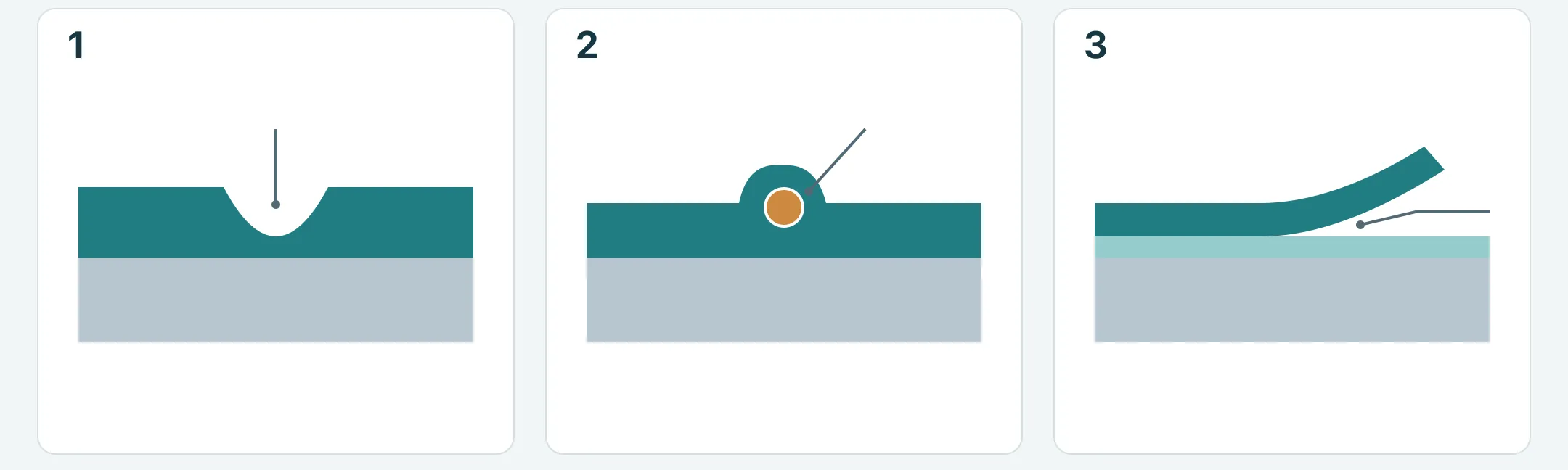
Pits in nickel deposits may involve attached bubbles, oily contamination or pre-existing substrate pores; raised roughness may involve particles incorporated during deposition. Both can look densely speckled, but they call for different corrections.[2]
Use oblique lighting and suitable magnification to assess surface relief, then a cross section if needed. Record magnification or a scale and keep the part orientation identifiable. Changing the lighting direction alone can make the shadow of a small bump look like a pit.
For upward-facing horizontal surfaces, check particle settling and filtration first. For inner bends, blind holes or pockets that can retain gas, check orientation, solution entry and bubble escape. Compare the same location before plating: corrosion pits, embedded particles and machining defects may remain visible afterward. These patterns help select tests; they do not replace the results.[1][2]
Do not blindly add wetter or brightener, or treat the entire bath, just because pits appear. Check analyses, addition records and filter maintenance first, then have process personnel run small controlled comparisons to distinguish particles, contamination, bubbles and substrate problems.
For burning, check local current conditions
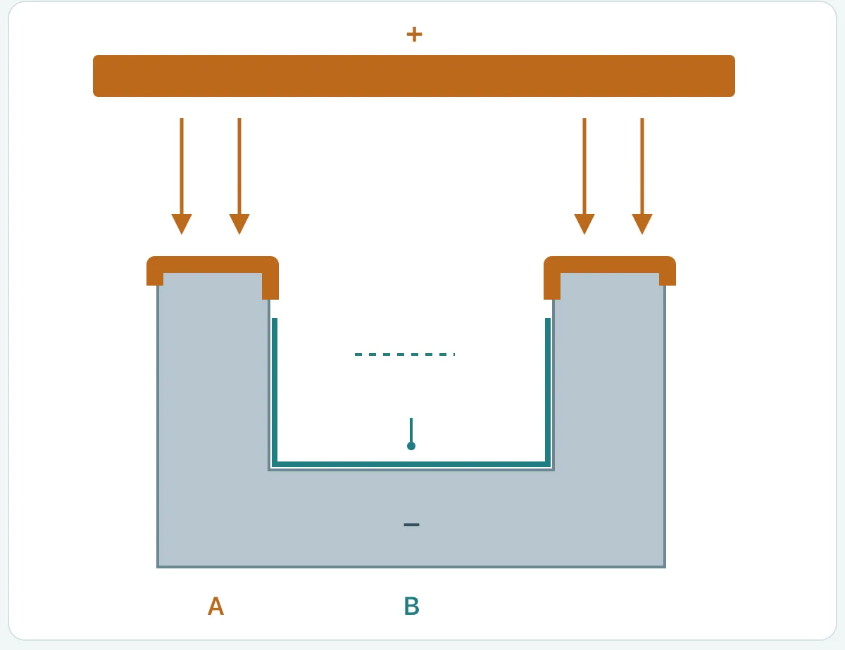
In plating, “burning” usually describes an abnormally rough, dark or otherwise poor deposit, not a part damaged by fire. In nickel plating, excessive local current density at edges and tips can cause this defect; low bath temperature or an imbalanced bath may aggravate it.[2]
Rectifier current is a total, not a statement that every surface receives the same current density. Projections, outer rack positions and surfaces closer to anodes may receive higher local current density than recesses, changing thickness distribution. Include part shape and racking in the investigation.[3]
Calculation example: ignoring exposed rack area, a total cathodic current of 120 A over 60 dm² of immersed, electrically connected part area gives an average current density of 2 A/dm². Reducing the area to 30 dm² while keeping 120 A increases the average to 4 A/dm². These numbers illustrate loading, not recommended process settings; local values on one part can still differ.
Mark defects on the part drawing and rack map, and check actual loading, immersion, current history, temperature and bath records. If edges burn while recesses remain thin, raising total current may worsen the edges. More targeted trials assess orientation, spacing, shields, auxiliary anodes or other current-distribution measures, followed by checks at critical locations on actual parts.[2][3]
Darkening alone does not establish burning. Use deposit morphology and the stage at which it appears to distinguish residues, post-treatment stains and other possibilities.
Distinguish missing coverage from locally thin plating
An uncoated surface and an existing but insufficient deposit are different conditions. Silvery substrates and silvery deposits can also mislead visual inspection. Select suitable thickness or cross-section checks for the coating system at both the suspect and adjacent sound locations.[6][7]
Poor electrical contact can interfere with deposition. Even with stable contact, geometric shielding, surface activity or retained gas can impair coverage. In multilayer systems, metallic luster at one location does not prove that every layer is continuous and complete.[2]
- Near contacts: confirm whether this is an agreed rack-contact zone, then inspect holding stability, contact condition and rack maintenance.
- Deep holes, inside corners or overlaps: check solution entry, gas escape, coating distribution and which measurement points are accessible.
- Isolated irregular patches: compare the preplating surface and cleaning/activation records for residues or local surface problems.
- Repeatedly at one rack position: compare material batches, rack positions and orientations separately to see whether defects follow the part or the position.
Acceptable thickness on an outer flat does not prove acceptable hole-bottom or inside-corner coverage. If a drawing requires continuous coverage or minimum local thickness at a location, specify that location and a feasible verification method. Agree on the area, size and functional limits of contact marks beforehand; do not dismiss them afterward as “normal rack marks.”
Align viewing conditions before tracing color variation
Color variation does not necessarily mean thin plating. Composition, surface morphology and post-treatment may also affect appearance. In zinc and zinc-nickel passivation systems, for example, process conditions affect color, while metal accumulation in the passivate can contribute to haze or discoloration.[4]
Compare samples under the same light, background and orientation. Establish whether the difference is color, gloss or surface staining. Phone auto white balance and reflection angles can mislead. If instrumental color differences are used, agree on settings, locations and criteria instead of applying one universal value to all metal surfaces.
Then compare retained samples by stage: was the difference already present after plating, or did it appear after passivation, sealing, drying or storage? Patterns along drainage paths or packaging contacts justify including rinsing, drainage, drying and packaging in the comparison. Locate the stage where appearance changes before deciding which bath or surface layer to analyze.[1][4]
An approved sample should identify the coating system, color and gloss, permitted variation and storage conditions. Passing appearance inspection does not automatically establish adhesion, corrosion resistance or electrical contact performance; accept these requirements separately.
Investigate six process areas with controls
Pretreatment, current, bath, rack, geometry and post-treatment interact, but checking all six mechanically from beginning to end is not always useful. Select checks that best distinguish causes using morphology, location and onset, then let the results guide the next step.[1]
| Investigation area | Records or parts to compare | Question to distinguish |
|---|---|---|
| Pretreatment | Unplated parts from the batch, cleaning/activation records, rinsing and transfer times | Does the defect follow the original surface or a particular processing stage? |
| Current | Actual conductive area, loading, current history, immersion and contact condition | Can local or transient conditions be abnormal despite a normal total setting? |
| Plating bath | Relevant analyses, temperature, filtration, additions and maintenance timing | Does the defect correlate with bath condition or a recent operation? |
| Rack | Contacts, insulation, positions, holding and maintenance records | Is the defect concentrated on a rack, contact or orientation? |
| Geometry | Holes, inside corners, gaps, overlaps and racking orientation | Are solution entry, gas escape, drainage or deposit distribution restricted? |
| Post-treatment | Comparative samples for passivation, sealing, rinsing, drying, storage and packaging | When is the defect first visible, and does it relate to a later surface change? |
Start with a small control set: keep untouched defective parts, sound parts from the same batch and unplated parts when available. Mark orientation and inspection locations on photographs, record batch, rack position and first detection time, and document each trial's change and the conditions held constant.
For ordinary troubleshooting, changing one main factor first makes effects easier to identify. Use designed, replicated trials when interactions need investigation. Validation should include the actual problem part and critical locations. Flat test panels can inform bath or property assessment but cannot alone prove that hole bottoms, contacts and recesses of complex parts comply.[1]
Reinspect reworked parts for the original use
Rework depends on the defective layer, substrate, dimensional allowance and service requirements. Concealing a visual defect does not prove that an adhesion problem has gone. Stripping and replating also require reassessment of substrate condition, mating dimensions and performance. Identify affected batches and their disposition, then use agreed checks to justify release.
| Requirement | What to record | Insufficient release evidence |
|---|---|---|
| Appearance | Significant surfaces, viewing conditions, approved sample, defect location and permitted severity | Casual photographs or “looks better than before” |
| Coverage and thickness | Coating system, local minimum, measurement locations, method and calibration | An overall average or one easy-to-measure outer flat |
| Adhesion | Method suitable for coating and substrate, test timing and acceptance criteria | Hand picking, ordinary tape or an unagreed substitute test |
| Assembly and function | Mating dimensions, subsequent bending, soldering, electrical contact and other actual requirements | Passing appearance and thickness checks alone |
X-ray spectrometry provides nondestructive thickness measurement for suitable coating systems, with applicability depending on the coating/substrate combination and other factors. Metallographic cross sections assess local thickness; reliable measurement of thin layers also depends on preparation and microscopy. Confirm that the selected method answers the question about the particular layer and location.[6][7]
For steels susceptible to hydrogen embrittlement, appearance inspection cannot replace the required controls. Determine post-treatment, sequence and verification from material condition and the applicable specification. A treatment that reduces susceptibility does not guarantee elimination of the risk, and no universal baking temperature/time should be assumed.[8]
Make defect records useful for the next discussion
Instead of “poor appearance,” give the fabricator or finisher a precise observation. For example: flaking occurs on the outside bend edges of brackets from the same batch; none has yet been seen on the inner flats; it was found before assembly and unreworked samples have been retained. This avoids assigning blame in advance while directly guiding interface, location and process checks.
On drawings, mark cosmetic faces, mating surfaces, electrical contacts and defects. Without complete drawings, start with overall and close-up photographs, substrate and known coating details, service environment, quantity and current questions. Mark unresolved thickness, color or acceptance details as to be confirmed and discuss them together.
At quotation stage, use the plating cost RFQ checklist to define thickness, scope and pricing conditions. When selecting a process, consult the powder coating, plating and anodizing comparison. For a specific part, submit available information through the drawing-review and quotation route.
- [1] N. V. Mandich and W. Saas — Troubleshooting Decorative Electroplating Installations, Part 1 (2000), pp. 121–124
- [2] Nickel Institute — Nickel Plating Handbook (2014), chapters 2, 10 and 11
- [3] Rachel Keatley, COMSOL — Optimizing the Electroplating Process for Multiple Components (2020)
- [4] MKS Atotech — EcoTri ONE: passivation for zinc and zinc nickel
- [5] ASTM B571-23 — Qualitative Adhesion Testing of Metallic Coatings
- [6] ASTM B568-98(2021) — Measurement of Coating Thickness by X-Ray Spectrometry
- [7] ASTM B487-24 — Measurement of Metal and Oxide Coating Thickness by Microscopical Examination of Cross Section
- [8] ASTM B850-98(2022) — Post-Coating Treatments of Steel for Reducing the Risk of Hydrogen Embrittlement