Deep drawing forms a hollow part by drawing surrounding sheet material into a die. For buyers and engineers reviewing a tooling concept, the useful question is not simply whether a die has a raised ring, but how that feature contacts the sheet and affects its movement.
1. First identify the ridge: three features can look similar
A view from above cannot establish what a raised ring does. Check a section through the tools and follow the sheet during closing and drawing. A drawbead typically has an opposing groove, with the sheet passing between them; it can be continuous, segmented or used only where extra restraint is needed. [1]
| Feature | What to look for | Main function |
|---|---|---|
| Drawbead | A narrow ridge and mating groove shape the sheet along its feed path | Add local drawing resistance and regulate material flow |
| Blank holder / binder | A broader surface presses the flange against the opposing tool | Support the flange against buckling and provide restraint through contact |
| Blank locator or locating step | A feature positions the blank edge before forming | Establish starting position; it is not automatically a drawbead |
2. Why the flange needs restraint
As a cup is drawn, the flange moves inward toward a smaller circumference. Circumferential compression can make this unsupported sheet buckle into wrinkles. The blank holder helps keep it supported while still allowing the material needed for the wall to feed inward. [2]
The wall also transmits the force needed to draw the flange. Increasing resistance can reduce uncontrolled draw-in, but it also raises the load carried by the wall. If material cannot feed sufficiently, local stretching and thinning can lead to a split. The aim is a workable balance, not the greatest possible holding force. [2][3]
3. Animation: follow the sheet over the bead
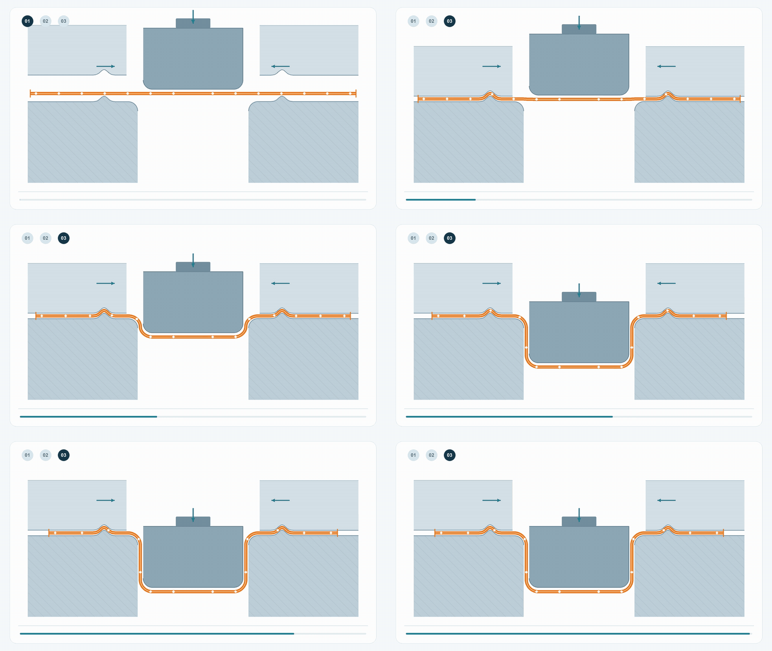
The animation begins with a flat blank above the open tools. The blank holder moves down and presses the flange over the drawbeads; then the punch descends through the die opening. Watch the orange sheet change from a flat strip into a cup while both outer edges move inward.
01 — The blank is flat. 02 — The holder closes and bends the flange over the beads. 03 — The punch draws the centre downward: material feeds across the beads, the cup walls grow and the bottom moves down. White dots follow the same material, making the deformation and inward draw-in visible. Bending, unbending and tool friction add feed resistance. [1]
This is a simplified cross-section of a generic cup. It shows the binder, punch, die and two local bead sections; an actual tool may have a continuous or segmented bead or place it on the other tool half. The motion illustrates material flow and changing shape, not a calculated press stroke, strain field or production die dimensions.
4. More restraint is not always better
Wrinkles and splits are symptoms to investigate, not unique diagnoses. Compare the defect location with flange draw-in, thickness measurements, lubrication and tool-contact conditions. [2][3]
| Observation | Possible connection to restraint | What to compare |
|---|---|---|
| Flange or wall wrinkles | Insufficient or uneven support or restraint may allow buckling | Where wrinkles begin; holder contact and gap; local draw-in |
| Localized thinning or a split | Excessive resistance may restrict feed and increase tensile loading | Minimum thickness location; bead engagement; radii; lubrication and material condition |
| Uneven draw-in or a skewed part | Restraint or friction may differ around the perimeter | Blank position; lubricant coverage; tool wear; measured draw-in at matched locations |
5. Does every deep part need a taller bead?
No. Depth alone does not determine whether a drawbead is required. Blank shape, material properties, thickness, corner radii, lubrication and the distribution of drawing demand all affect the solution. Some parts can be drawn with a suitable blank holder and no drawbead; others need restraint only in selected regions. [2][4]
Bead height, radius, section and engagement must be considered together with holding conditions. A taller or sharper bead can increase deformation and resistance, but it can also increase thinning, surface damage or splitting risk. There is no universal bead height that guarantees a deeper draw. [1][3]
A bead also does not prove that a tall shell can be made in one draw. Blank development, draw ratio and any redraw operations require a separate process assessment. For the distinction between forming operations and tooling arrangements, see the related process comparison.
6. A practical way to review a trial part
Agree what evidence will show that a change helped. Keep the material batch, blank, lubrication and press setup traceable, then compare controlled trials rather than changing several settings at once.
- Mark corresponding positions around the starting blank and record local flange draw-in after forming. Compare all relevant sides, not just the overall part depth.
- Measure thickness at the wall, punch radius and other suspect locations using a suitable method. Record the minimum thickness and where it occurs, alongside wrinkles, cracks and surface marks.
- Review holder contact, bead engagement, tool radii and lubricant coverage with the toolmaker. Select a specific adjustment and compare its result with the baseline.
- Check the finished functional dimensions and assembly requirements as well as appearance. Confirm that any improvement remains consistent across repeat trial parts.
For example, with an initial thickness t₀ = 1.00 mm and a measured local thickness t = 0.82 mm, local thinning = (t₀ − t) / t₀ × 100% = 18%. This is a calculation example, not an acceptance limit. Define the allowable result from the part requirements, material and forming assessment; one thickness reading does not establish that the whole part is sound.
- [1] WorldAutoSteel — Friction and Friction Testing: drawbead bending, unbending and friction
- [2] WorldAutoSteel — Drawing: flange stresses and blank-holder support
- [3] WorldAutoSteel — Forming Strategies and Solutions: balancing wrinkles and splits
- [4] WorldAutoSteel — Correcting Springback: application-specific binder and bead arrangements