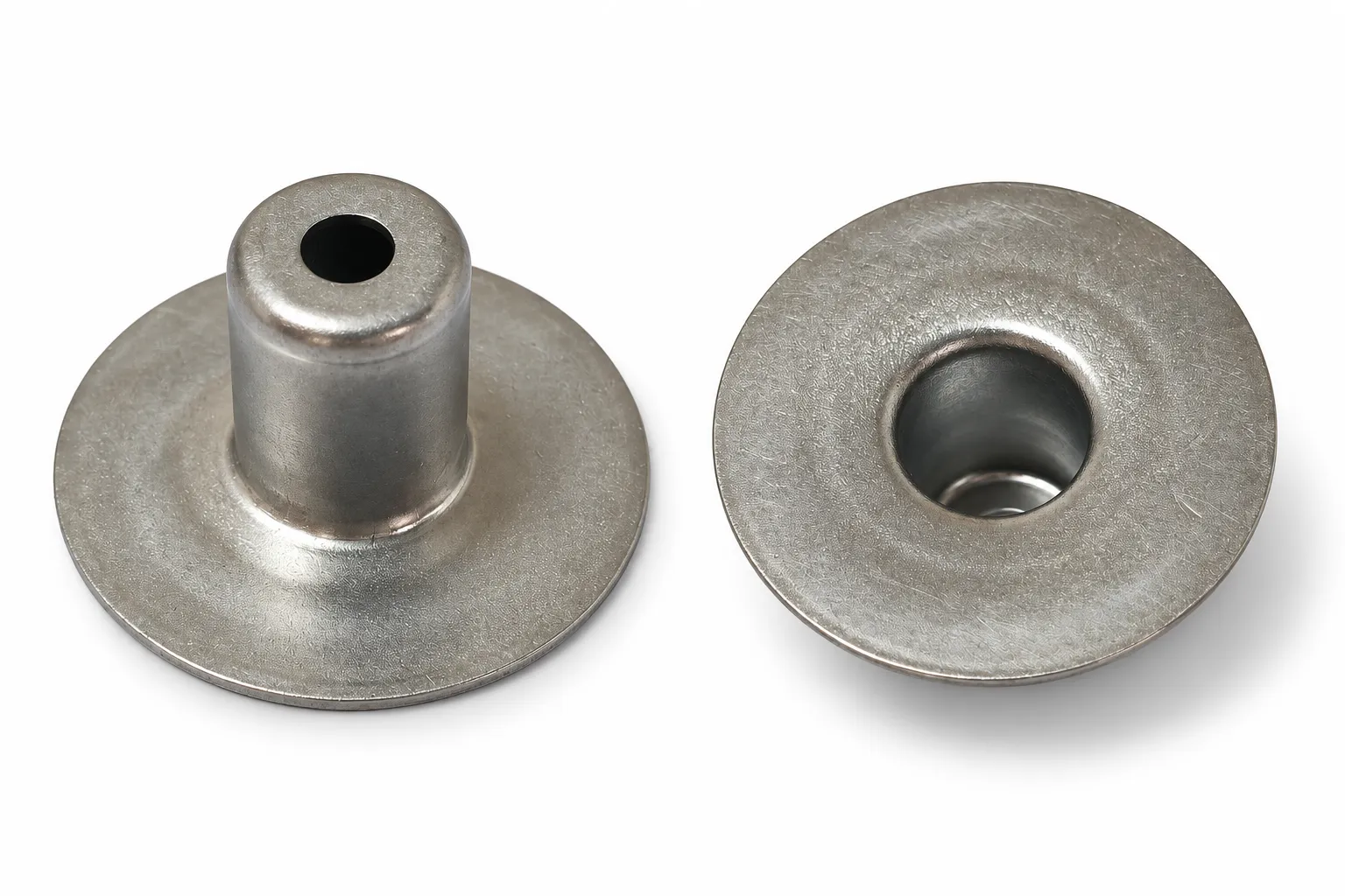
Flanged drawn cups and cylindrical drawn shells describe the geometry of drawing-defined components. The illustrated cup retains annular material at the barrel end around a central aperture, which is specified separately from the larger cavity.
For a custom part, flange dimensions establish the mounting contact, barrel dimensions relate to the assembly space, and the end hole relates to a shaft, guide rod or interface. The following manufacturing and purchasing details support enquiries from buyers with an existing drawing or assembly requirement.
Flanged metal cup and cylindrical shell geometry
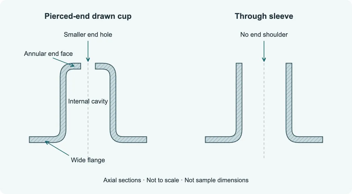
The smaller end hole may pass a shaft or guide rod while the larger cavity clears other components. The remaining annular end face may act as a shoulder or contact surface. The assembly drawing must establish whether contact is allowed and whether that face carries axial load.
The flange can provide an assembly face or stop insertion, but it does not automatically prevent withdrawal. The illustrated geometry has no visible flange mounting holes, thread or locking feature. Retention therefore needs its own design, such as capture by mating components or a specified joining method; a flange alone does not establish direct screw mounting.
Stepped cup with center and side holes
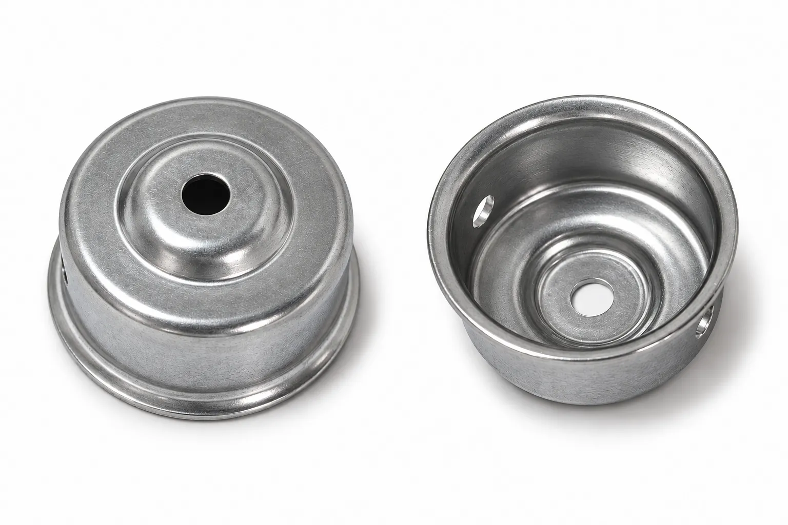
This sample has a short cylindrical wall, a flared rim and a stepped end face surrounding a small circular opening. The reverse view shows the larger cavity and visible sidewall holes. These features provide a useful starting point for specifying covers and end interfaces for small electromechanical assemblies.
The center hole may clear a shaft, guide rod or interface. The cavity provides space around internal components. A step changes the local profile and may form part of a mating surface. The assembly defines whether any surface locates, contacts or carries load. Material remains around the end hole, so this geometry differs from an entirely open sleeve.
Side holes also need a stated function. Assembly access, cable passage and ventilation require different locations and edge conditions. Their actual role cannot be determined from these photographs. The material, finish, dimensions and end product remain unconfirmed.
Deep drawing, end piercing and secondary operations
A candidate route is blank preparation, drawing a flanged cup, any necessary redrawing or sizing, trimming and end-hole production, followed by deburring and finishing. Trimming and piercing after forming are established operations, but the sequence and number of operations depend on material, geometry, tool support and dimensional requirements.
If the end hole must locate relative to the barrel axis or flange datum, consider how the cup is located and supported during hole production. Hitting the hole diameter alone may leave its position unresolved. A thin end face can also deform during piercing or assembly. Recheck functional dimensions after operations that can affect them.
Specify material grade, starting sheet thickness and delivery condition through the drawing or material record. A silver-grey surface does not establish stainless steel or a zinc or nickel finish. Wall, end-face and corner thickness deserve separate attention; starting sheet thickness is not a substitute for all finished measurements.
Custom dimensions, materials and drawing requirements
Mark the actual contact surfaces before assigning dimensions and tolerances. Every visible contour does not need the same control: features responsible for assembly, movement or load deserve priority.
| Feature or input | What to define | Assembly question answered |
|---|---|---|
| Flange | Outside diameter, actual contact area, flatness needs, retention and corner clearance. | Will the flange seat, or will its root radius hold it away? |
| Barrel and cavity | Outside and inside diameters, usable depth or height, with the height reference face stated. | Will it enter the mating hole, and will the internal component fit? |
| End face and smaller hole | Hole diameter, location relative to functional datums, contact area and edge condition. | Will the shaft or rod rub, and does the face carry force? |
| Material and surface | Grade, sheet thickness, delivery condition, finish, cleanliness and appearance requirements. | Can it be formed, and will corrosion, wear or electrical contact affect use? |
| Sample acceptance | Drawing revision, mating parts, installed condition, inspection method and protective packaging. | Does the accepted free-state part still work after installation? |
Clearance example: with a minimum end-hole diameter of 6.20 mm and maximum shaft diameter of 6.00 mm, ideal concentric radial clearance is (6.20 − 6.00) / 2 = 0.10 mm. A relative axis offset of 0.08 mm at that section leaves only 0.02 mm on the tighter side. This assumed example excludes roundness, tilt, operating deflection, temperature and surface layers. It explains the geometry; it does not select a working clearance.
Drawing requirements for motor shrouds, sensor housings and spring cups
Motor shrouds, sensor housings, spring cups and lighting covers have different mating and acceptance requirements. Drawn components for motor, sensor, lighting and HVAC products are documented families. The table associates those names with drawing requirements; the supplied product identity follows the actual customer drawing, and the illustrated sample is not identified as any one finished product.
| Part name or application | Relevant geometry | Drawing and acceptance requirements |
|---|---|---|
| Small electromechanical products: fan motor, geared motor or actuator shaft-end cover | The flange meets the housing, the cavity clears components and the smaller hole passes the shaft end. | Running clearance, hole location relative to assembly datums, rotating envelope and retention. A bearing-supporting end cover also needs a defined seat, stiffness and life requirements. |
| Industrial sensing and instruments: probe or position-sensor mounting shroud | The cavity receives components, the end hole meets a probe or interface, and the flange provides an assembly face. | Interface dimensions, insulation or grounding, lead protection, installation direction and ingress requirements. A pierced shell is not a closed protective probe tube. |
| Valve and temperature-control actuators: spring-location or travel-stop cup around a guide rod | The wall may locate a spring end; the annular end face may receive spring force; the hole clears the rod. | This is a geometry-based design hypothesis. Establish spring contact, preload, travel, local deformation and cycle life. Documented HVAC cups do not establish a pressure rating for this sample. |
| Lighting hardware: mounting shroud or decorative cover around a lamp-stem interface | The flange covers the surrounding assembly edge, the barrel clears the interface, and the hole passes a mating tube or wiring assembly. | Edge protection, retention, electrical clearances, temperature and finish requirements. The metal cover alone is not a qualified lampholder or electrical insulator. |
Cover drawings first establish space, the end opening and retention. Spring cups, moving guides and bearing-supporting parts add load, contact, motion and validation requirements. Similarly named drawn parts need quotations based on their own assembly drawings and acceptance criteria.
Drawn-part samples and installed-part inspection
First-article checks can cover flange seating, barrel dimensions, cavity depth, the end hole and its location, followed by assembly with the mating parts. Passing a gauge through the end hole does not also prove the hole is correctly located relative to the barrel. If clamping can dish the end face, recheck under the agreed installation condition.
For a cover, check moving-part clearance, retention and edges near wiring or hands. For a spring-location cup, add contact-area deformation and cyclic validation. Bearing support adds seat geometry, axis relationships, retention and load validation. Fluid contact requires a defined medium, joint, seal, pressure and leakage acceptance method.
These requirements belong in sample approval. A product photograph or a description of seamless construction cannot establish them. Holes, joints and surface defects can change the protection or sealing performance of the complete assembly.
Drawings and information for a custom-part enquiry
Send a drawing, sketch or photograph and explain where the flange sits, what occupies the cavity, what passes through the end hole and the expected quantity. Unresolved dimensions, material or retention can be marked for discussion; a mating-part drawing and the current assembly problem are useful starting points.
Also distinguish a bare drawn part from a finished part or an assembly containing other components. Sample approval and repeat batches should refer to the same drawing revision and agreed acceptance conditions.