How does PVD deposit material on a part?
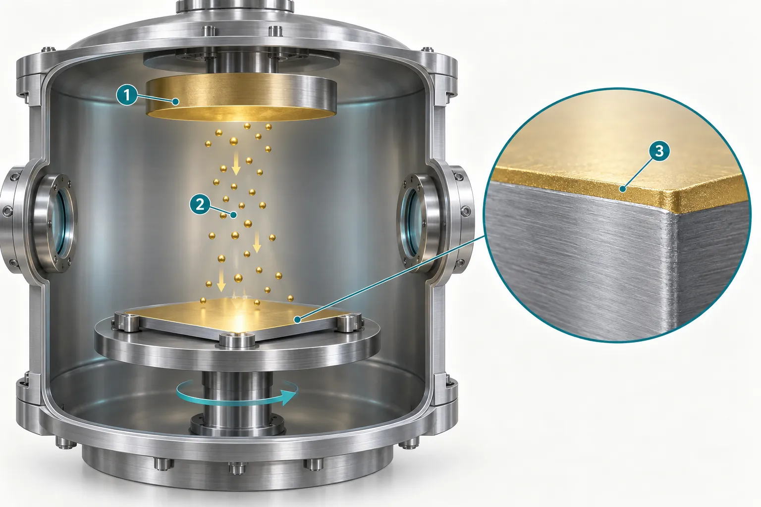
PVD means physical vapor deposition. Coating material is released as atoms, molecules or ions in a vacuum or low-pressure environment, travels through the chamber and forms a thin film on the workpiece. Nitrogen, oxygen or carbon-containing reactive gases can produce nitrides, oxides or carbides. [1]
Common routes include evaporation and sputtering. Evaporation releases material using heating, electron beams or arcs; cathodic arc is one example. Sputtering ejects material from a target by energetic particle bombardment, with magnetron sputtering a common implementation. Ion bombardment, substrate bias, temperature and reactive gas conditions influence structure and adhesion. [1]
PVD, electroplating and ‘titanium coating’ are not interchangeable names. Electroplating deposits material through electrochemical reactions in an electrolyte; PVD is a family of vacuum processes. ‘Titanium coating’ can be a commercial description of a decorative finish. Specify the actual process and coating, or ask for a system that can be validated for the application. DLC, diamond-like carbon, names a coating category that can be made by PVD or other routes; its name alone does not identify the deposition method. [1]
Surface preparation already determines part of the outcome
PVD normally retains the underlying topography. It should not be expected to level obvious welds, irregular brushing or grinding depressions. Mirror versus brushed surfaces, brushing direction and excessive weld dressing can all become more apparent after coating. Decorative coating suppliers also identify retention of substrate texture as a product feature. [1][2]
The following sequence explains the process chain; the exact operations depend on substrate and coating architecture:
- Complete machining and surface preparation: confirm forming, welding, deburring, polishing or brushing on visible areas; resolve obvious substrate defects before coating.
- Clean and control contamination: remove oil, polishing residues and unsuitable contamination. Storage, handling and fixturing after cleaning can recontaminate surfaces.
- Fixture, mask and treat in vacuum: apply heating and ion etching as required, with planned orientation and rotation. Conditions affect interfacial bonding and subsequent growth.
- Deposit, cool and inspect: check color, coverage, defects and specified performance, then protect visible surfaces during handling and assembly. [1]
Check whether the workpiece can tolerate the complete thermal process. Installed plastics, adhesives and seals cannot be judged compatible merely because the PVD film is thin. Temperatures vary between processes; one fixed temperature cannot characterize all decorative PVD. [1]
For coating before bending, validate cracking and peeling with representative bend radii, material condition and appearance requirements. Completing major forming first reduces subsequent deformation risk but increases coverage challenges in grooves and internal corners. Compare both sequences using finished geometry.
Why can a matching front face have different grooves and internal corners?
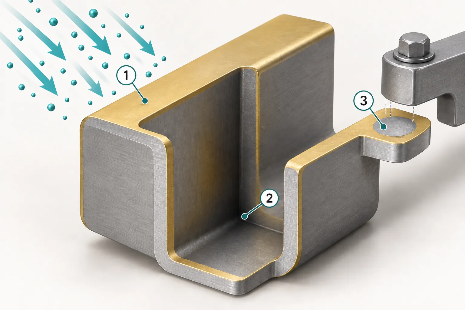
Material transport in PVD is strongly directional. Faces exposed to the source receive particles more readily; groove bottoms, folded internal faces and regions screened by other parts may receive them differently. Pressure, ionization, bias and rotation influence coverage. Rotation does not mean that arbitrary holes or deep grooves will be coated uniformly. [1]
A flat color coupon mainly answers whether shade and texture are acceptable. A formed part is more suitable for confirming whether the required surfaces can meet requirements together. Mark visible fronts, folded edges and interface surrounds on enclosure drawings, and state whether backs, holes and fixture points may remain uncoated or differ visually.
Arrange fixture contacts before sampling. Define acceptable contact positions and check whether production fixturing can reproduce them. Thickness measurements should include representative faces and risk locations; a separate witness coupon does not automatically represent every region of the finished part.
How do gold, gunmetal and black relate to coating materials?
Commercial color names describe appearance, not chemical composition. TiN and ZrN can produce gold-colored finishes without implying gold content. Dark films can use DLC, some carbides or other composite systems; black is not necessarily DLC. [1]
| Appearance | Coating categories to discuss | What else to confirm |
|---|---|---|
| Gold-colored | TiN, ZrN or related composites | Shade, brightness, substrate texture and batch consistency; the name does not prove gold content. |
| Silver gray or gunmetal | Chromium-based, nitride and other decorative systems | Physical sample and actual formulation; suppliers’ gunmetal shades can differ substantially. |
| Black or dark | DLC, carbides and related composites | Actual material, deposition route, gloss and adhesion; color alone does not establish performance. |
These are candidate directions, not unique recipes. Shade and performance vary with formulation, architecture and deposition. [1] For adjacent panels, approve substrate, texture and color together. Mirror and brushed finishes reflect light differently and can look different even with the same coating category.
Agree illumination, viewing angle, brushing direction and inspection locations for color approval. If quantitative comparison is needed, record CIELAB values and define the color-difference formula and tolerance. Instrument geometry, gloss and texture matter; one ΔE limit is not universal for metallic finishes. [1]
Why can a hard coating still scratch or peel?
Hardness describes resistance to local indentation; wear describes material loss under specified contact; adhesion concerns bonding to the substrate or between layers. These properties are related but answer different questions. A thin hard film over a softer substrate can crack when concentrated loading deforms the substrate; inadequate interfacial bonding can cause local peeling. [1][3]
A study of shot peening and TiAlCuN coatings on additively manufactured 316L linked scratch failure to substrate support, surface condition and coating bonding. Its loads and hardness results cannot become acceptance limits for ordinary stainless sheet metal. Its useful implication is to assess the complete substrate–interface–coating combination. [3]
Repeated hand contact, hinge sliding, key impacts and wiping with particle-containing cloths are different contacts. Define the counter material, load, cycles, liquid or particles, and failure criteria. Visible scratches, exposed substrate, color change and peeling need not share one criterion. [1]
Instrumented scratch results also need the probe, loading program and failure definition. A critical-load value without these conditions does not describe how many everyday impacts a part can tolerate. If appearance retention is the objective, examine visible changes after testing rather than reporting hardness alone.
Does PVD always improve stainless steel corrosion resistance?
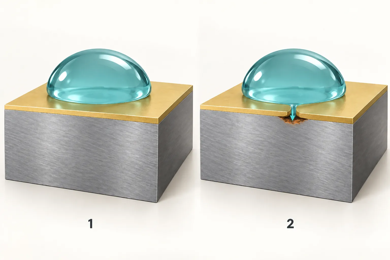
Not necessarily. A continuous, dense film suitable for the environment can act as a barrier, while pinholes, microcracks and incomplete coverage can let media reach the substrate. Grade, initial surface condition, coating architecture and exposure all influence the result. [1][4]
Staszuk et al. compared CrN PVD and CrN/TiO₂ hybrid films on ground and polished 316L coupons, with a CrN layer of approximately 2 μm. In room-temperature electrochemical testing in 3.5% NaCl, CrN alone did not improve the measured corrosion behavior; an appropriate ALD titanium oxide layer improved related indicators. ALD is a different deposition method: these results concern a specific hybrid system, not all PVD. [4]
In that study, the best corrosion variant was not necessarily the best friction variant. A thicker titanium oxide layer showed brittle cracking and spalling in the specified contact tests. ‘Thicker is better’ is therefore insufficient. Evaluate corrosion, friction, adhesion and appearance together when considering an additional sealing layer. [4]
Frequently touched parts also warrant sweat exposure assessment. Carneiro et al. tested chromium-based decorative films on base-coated AA5052 aluminum in a defined artificial sweat, observing different electrochemical and surface changes over exposure up to 96 hours. Aluminum was the substrate, not stainless steel. The work supports selecting an exposure test for touch applications, but does not establish stainless finished-part sweat lifetime. [5]
The public significance-and-use statement for ASTM B117-19 explains that salt-fog results alone generally do not predict natural-environment performance; its scope does not prescribe product exposure times or interpretation. Test hours cannot be directly converted to outdoor years. Specify the method, specimen state, exposed regions and failure criteria, using the standard edition required by the project. [6]
Turn appearance requirements into finished-part acceptance
Select acceptance items from actual use before choosing measurement methods. Color and coverage may take priority for decorative panels; wear and adhesion matter more for sliding contacts; sweat, salts and cleaners call for additional environmental assessment.
| Acceptance item | Objects and method arrangements | Criteria to define in advance |
|---|---|---|
| Appearance and color | Approved actual substrate/texture; fixed lighting, angles and locations | Color and gloss variation, particles and visible defects; comparison between adjacent assembled parts. |
| Coverage and thickness | Fronts, folds, grooves and other risks; method suited to material and layers | Requirements at defined positions, uncoated or masked regions, total or individual-layer thickness. |
| Adhesion and wear | Scratch, indentation or application friction tests suitable for the film | Conditions and criteria for cracks, peeling, exposure and scratches; ‘good adhesion’ alone is insufficient. |
| Environmental resistance | Corrosion, sweat, cleaning or damp heat as appropriate | Medium, temperature, duration, edge state and acceptable discoloration, corrosion or peeling. |
| Later processing and assembly | Actual bending, fastening, contacts and packaging | Permitted post-coating work; treatment and acceptance for fits, fixture marks and contact regions. |
Thickness methods and calibration must suit the coating and multilayer architecture. Cross-sectional analysis can reveal layers directly; XRF suitability depends on coating, substrate and measurement model. A displayed instrument number does not itself establish method suitability. [1]
Specify functional contacts separately. Grounding, electrical contact and tight fits require actual assembly validation and masking where needed; decorative coating names alone do not establish contact performance.
Start with a practical equipment-panel example
Consider an indoor stainless equipment panel with a gunmetal brushed finish, visible front and two folded edges, frequent contact around buttons, and a rear assembly contact. Start with these arrangements:
- Mark matching-color regions, brushing direction and acceptable fixture contacts on the drawing; specify separate treatment requirements for assembly contacts.
- Produce flat color coupons using actual substrate and prepared texture to approve shade and gloss.
- Coat parts after principal bending and surface preparation, then examine folds, hole mouths, internal corners and fixture points.
- Add checks around buttons that represent actual touch and wiping; record cleaner and acceptance criteria.
- Retain approved color coupons, finished samples and regional requirements together, and compare later batches under the same conditions.
This is a requirements example, not a universal thickness, color-difference or test-duration specification. Compare cost for the same accepted finished part, including preparation, fixturing, masking, inspection and packaging. Comparing the coating operation alone can omit work needed to deliver the part.
- [1] Vorobyova et al. PVD for Decorative Applications: A Review. Materials 2023, 16:4919
- [2] Ionbond IHI Group. Decorative Coatings
- [3] Bonnici et al. Additively Manufactured 316L Stainless Steel Subjected to a Duplex Peening-PVD Coating Treatment. Materials 2023, 16:663
- [4] Staszuk et al. Investigations of CrN/TiO₂ Coatings Obtained in the Hybrid PVD/ALD Process on 316L Steel Substrates. Materials 2026, 19:1921
- [5] Carneiro et al. Corrosion Resistance in Artificial Perspiration of Cr-Based Decorative Coatings. Nanomaterials 2023, 13:2346
- [6] ASTM B117-19 — official public scope and significance-and-use statement