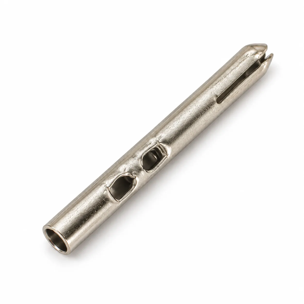
The same hollow profile can be used to carry a mating component, sit inside a molded support or form part of an electrical connection. Before choosing tooling or a product name, establish what each surface, opening and end must do.
The photographs supplied for this sample show an open thin-wall end, two adjacent side openings and a narrow slot near the opposite end. The white-background images are AI-retouched presentation views. Use the original sample and drawing to establish geometry; the images do not establish dimensions, alloy, plating or performance.
Start with the visible structure, then define its job
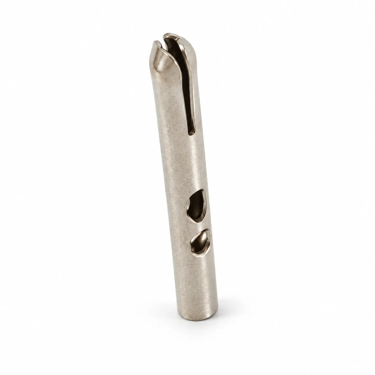
The visible edge and apparent longitudinal joint make a rolled-sheet route plausible. They do not prove the manufacturing history. A drawing, a flat blank or an in-process sample would help distinguish rolled sheet from a tube-based route.
Use a neutral description—slotted hollow metal tube with side holes—until the mating relationship is known. If the part is an electrical contact, confirm whether the slotted end enters a socket or receives a pin. An opening alone does not identify a male or female contact.
| Visible feature | What to establish |
|---|---|
| Hollow body and open end | Does the bore locate a component, accept a wire, receive molding material or provide clearance? |
| Two adjacent side openings | Are they retention, process-access or another functional feature? Locate them from the relevant assembly datum. |
| Long slot and split end | Is elastic movement required? Define the mating component, working travel and allowable permanent deformation if so. |
| Apparent longitudinal joint | Is an open seam permitted, or is a closed or joined seam required? Confirm clearance and orientation. |
A candidate route: pierce, preform, roll and size
Rolled-sheet hollow plug pins with a longitudinal joint are a documented construction.[1] For a part of this general shape, a useful process proposal starts with a flat blank and reviews the local openings together with the later tube shape. The sequence below is a candidate for discussion, not a record of how this sample was made.
- Confirm strip material and thickness from forming and service requirements. Define which direction the seam and critical edges may face.
- Pierce the side holes, cut the slot and develop the blank outline while the stock is flat, where practical. Reserve enough material for the end shape and subsequent forming.
- Preform the blank, then roll it around suitable tooling toward the required tube section. Control the relative position of the holes, slot and seam.
- Form the end and size the tube as needed. Review springback, ovality and local deformation around the openings with trial parts.
- Plan edge treatment, cleaning and any specified finish. Inspect the part in its delivery condition, including dimensions affected by the finish.
Pre-piercing provides access to a flat surface, but the holes can change shape during rolling. If a hole controls fit or location, define its final formed dimensions and assess whether a later operation is needed. The final operation order and station count depend on the drawing, material and tooling trials.
Repeated demand and a stable design can justify evaluating a progressive die. Compare tooling, yield, finishing, inspection and maintenance over the expected order quantity; a hollow shape alone does not establish a cost saving.
Why the side holes and end slot need separate decisions
In some hollow plug-pin designs, molding material passes through a side opening into the bore and connects with the plastic support. This creates mechanical retention against movement; it is a documented role for side passages, not proof of the role of this sample’s two holes.[1][2]
If the slot is intended to let the end deflect during mating, its length, width, root shape and edge condition become working features. Specify the mating part and required travel before deciding how much movement is acceptable. If elastic movement is not required, do not treat the slot as a spring specification.
Also decide whether the joint must remain open, close during sizing or receive a joining operation. The welded seam in one plug-pin design is a feature of that construction; it is not a requirement for every rolled tube.[1]
Potential application industries for related hollow parts
Related hollow pins and stamped contacts are used in electrical products, but the assembly and qualification determine suitability. The examples below identify industries worth discussing; they do not establish where this particular sample has been installed.
| Industry | Related application | What would connect this sample to that use |
|---|---|---|
| Power plugs and cord sets | Hollow plug pins retained in a molded plastic support.[1][2] | Pin geometry, wire termination, molding boundary and the applicable product requirements. |
| Chargers and power adapters | Integrated hollow-pin plug frames are described for chargers.[3] | The complete plug layout, housing retention, electrical design and assembly validation. |
| Sockets and electrical installation products | Hollow pins are offered for sockets and multiple sockets with a grounding pin.[4] | Whether the part is a current-carrying or protective-earth component, and its actual connection and retention. |
| Industrial and vehicle connectors | Manufacturers offer stamped and formed contacts for industrial machinery and transportation systems.[5] | A matching contact system, mating geometry, termination and environmental requirements; this is a broader part category. |
Do not select an application from visual resemblance alone. A plug pin, a socket contact and a non-electrical locating sleeve can have similar hollow sections while requiring different materials, tolerances and tests.
Material and finish follow the required function
A silver-colored surface does not identify stainless steel, a copper alloy or a particular plating. For electrical duty, establish the current path, mating action, environment and termination before selecting a material and finish. For example, TE offers its own stamped-contact families with different interface finishes; those options and product ratings belong to the specified contact system.[5]
For a locating or support function, prioritize fit, stiffness, edge condition and the service environment. Do not specify an electrical contact alloy merely because the part resembles a pin. In either case, agree which dimensions apply before and after any surface treatment.
Approve the formed part in the intended assembly
Measure the features that control function, then assemble the sample with its actual mating parts. A loose tube can meet a diameter check yet change shape when it is pressed, crimped or molded into another component. Define whether acceptance applies before assembly, after assembly or at both stages.
| Review area | What to agree |
|---|---|
| Tube section | Outside diameter, bore, length, wall thickness, roundness and measurement positions. |
| Holes, slot and seam | Final dimensions and datums, seam gap and orientation, permitted local deformation and edge condition. |
| End and mating surfaces | Entry shape, engaged length, clearance and any required elastic movement. |
| Retention and termination | Molding or joining boundary, assembly method and an agreed retention or pull-out test where applicable. |
| Electrical duty, if required | Contact resistance, temperature rise, insulation and durability checks selected for the complete product; requirements and limits must be specified. |
| Delivery condition | Material and finish identification, appearance reference, cleanliness and packing that protects the slotted end. |
Start the discussion with a drawing, sketch or sample photograph. Mark which end mates, where the part is retained and whether it carries electricity. Add the expected quantity and the questions still open; material, dimensions or finish can remain marked “to be confirmed” while the requirements are discussed.