An aluminum cover may use stainless screws because the screws and the cover have different jobs. Trouble is often concentrated at a hole, seam or retained droplet, so start the review at those locations rather than approving or rejecting the entire assembly from two material names.
This guide helps engineering and purchasing teams decide what to check before releasing an enclosure joint. Keep the corrosion decision connected to the drawing, finish, fastener stack and electrical function.
First check whether the joint can form a corrosion cell
In an aluminum–stainless pair, aluminum normally acts as the anodic member and can lose metal preferentially when the galvanic cell is active. The metals need an electrical path and a shared conductive liquid; rainwater, condensation or salty moisture can provide that liquid. More conductive contamination can make the exposure more demanding. [1]
Use the location on the enclosure to make that mechanism concrete. Can liquid reach the screw and adjacent aluminum? Does it remain under the head or inside the overlap? Are the two metals connected through the shank, a metal washer, the bracket or another part of the assembly?
Galvanic corrosion and crevice corrosion are different mechanisms. A stainless joint may suffer crevice corrosion without an aluminum member. For this material pairing, evaluate the galvanic path as well as any trapped-liquid geometry; a single cause should not be assigned from a photograph alone.
Compare the areas that are actually exposed and wet
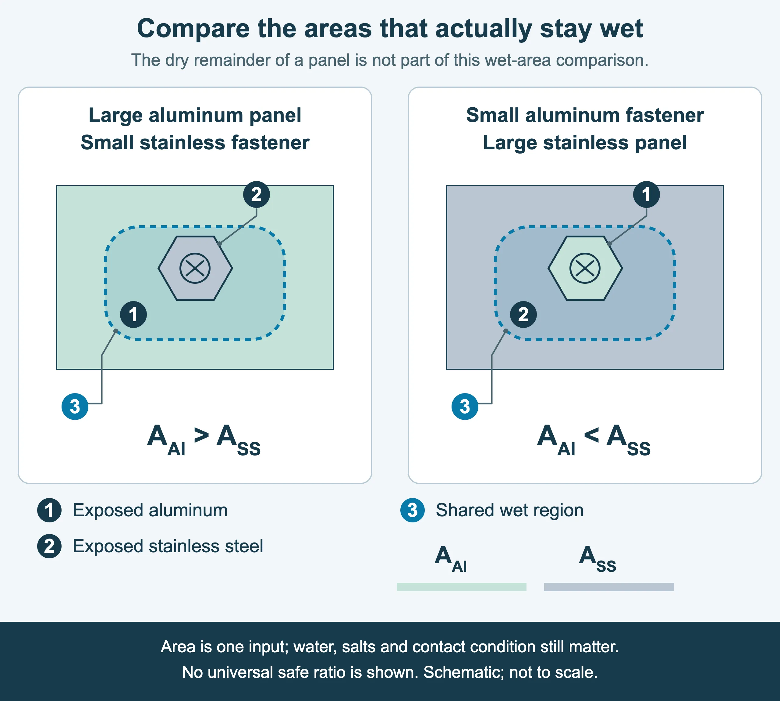
The relative areas of the anodic and cathodic surfaces influence the risk. A small anodic area coupled to a much larger cathodic area is generally a less favorable arrangement. That is why a small aluminum rivet joining stainless sheets deserves a different review from a small stainless screw in an aluminum panel. [1]
The area to consider is the surface participating in the wetted connection, not simply the dimensions of the whole panel. A coating defect beside a screw can leave only a small aluminum area exposed. The electrolyte distribution and coating condition can change the effective relationship. [2]
Treat the comparison as a reason to inspect the joint, not a pass/fail rule. Salt-bearing moisture and persistent wetting can still damage aluminum around stainless fasteners. No universal safe area ratio is assigned here. [1]
Trace contact through the head, hole wall and opposite face
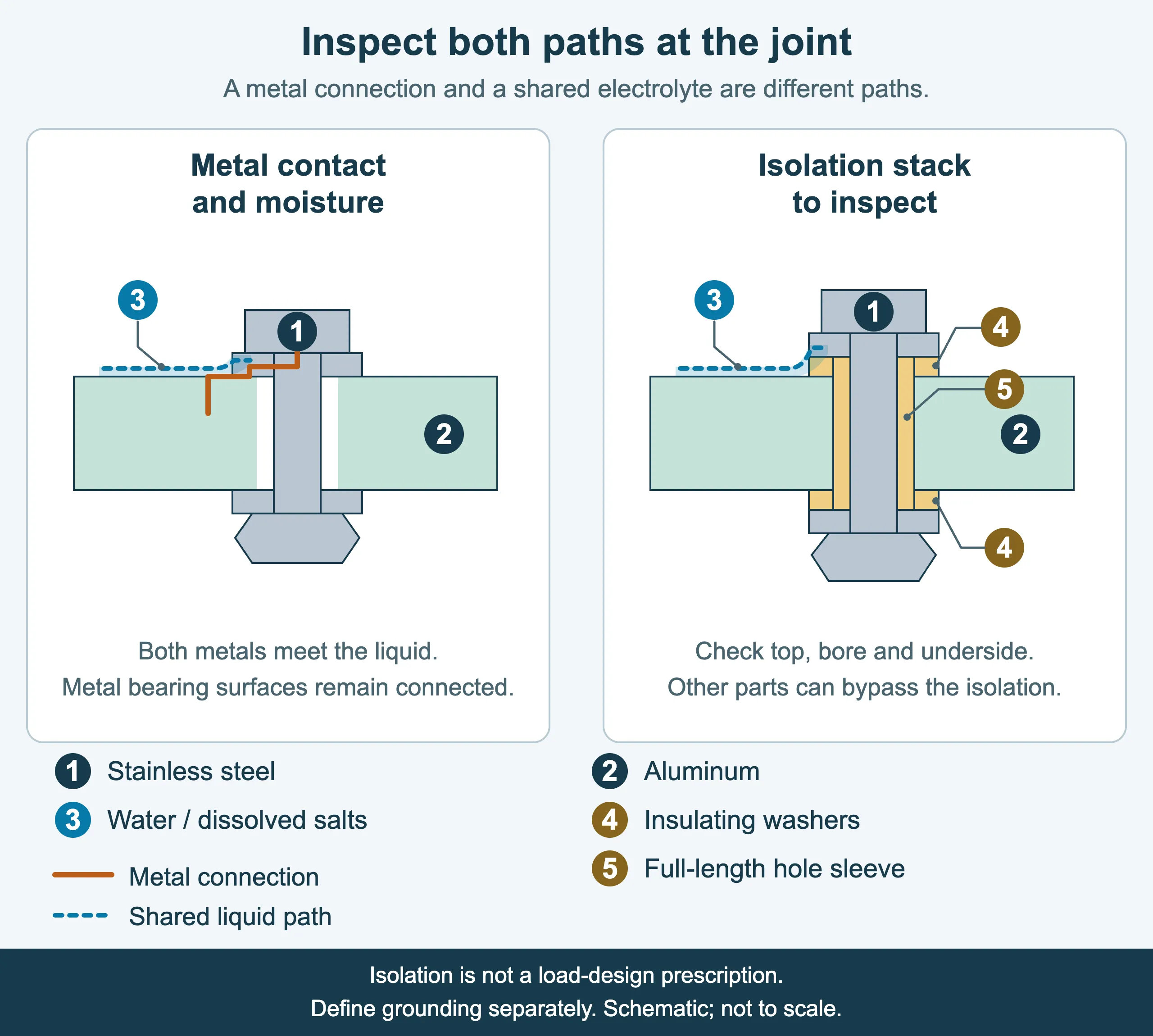
If electrical isolation is part of the chosen strategy, draw the complete fastener stack. An insulating washer under the head leaves a conductive route if the shank touches the aluminum hole wall, a thread engages bare aluminum or a metal washer on the opposite face bridges the parts.
A sleeve and washers can illustrate how contact paths might be interrupted. The sleeve needs to cover the relevant hole-wall contact, and the other bearing face also needs review. Other conductive parts can bypass this local isolation; check brackets, hinges, inserts and the intended bonding path across the assembly. [2]
Use the drawing to specify the intended isolated contacts and the contacts that must remain conductive. A through-bolt sketch does not define a solution for a tapped aluminum hole or a self-clinching insert. Those joints have different geometry and installation requirements.
Protect the joint where coatings and water paths meet
Review the finished hole, cut edge and bearing surfaces rather than relying on the appearance of a coated panel. Assembly, tightening or later service can leave an exposed location. If only the anodic member is coated, a small coating defect can concentrate the exposed anodic area; coating both members is a corrosion-control option where compatible with their functions. [2]
Anodizing or paint should be specified with its actual coverage and acceptance requirements. A finish name does not establish electrical isolation across a screw thread or a scratched hole wall. Check the delivered assembly rather than assuming that every surface remains covered.
Decide where liquid should drain and how a seal will be applied and inspected. A sealant should address the intended wetting path, while the selected construction must still permit assembly, maintenance and the required electrical contacts. Record the seal location and accessible inspection points on the drawing.
Check the load path before adding insulating parts
An insulating component also becomes part of the mechanical joint. Review its bearing load, thickness, temperature range and long-term dimensional behavior, together with the fastener engagement and assembly procedure. Thermoplastic parts can creep under sustained load, with temperature affecting their behavior; the material needs a joint-specific review. [3]
Changing a washer, coating or lubricant can change the stack and the friction associated with tightening. Tightening torque does not map to the same clamp force for every surface condition. Select the material and assembly procedure from the actual joint requirements, and define what is tightened, how it is checked and whether service replacement changes the approved stack. [6]
For a removable cover, include repeated opening in the sample plan. For a loaded bracket, identify the structural acceptance criteria. Corrosion mitigation should be approved together with the joint's mechanical function.
Keep isolation and required bonding on the same drawing
A connection intended to isolate metals and a connection intended to carry current have different requirements. Identify protective bonding, a functional ground or a shielding contact by its required function rather than treating every screw as an interchangeable grounding point.
One approach for review is to define where isolation is required and where a controlled conductive connection is required. That conductive location needs its own material, surface, wetting and maintenance review; it can also electrically reconnect parts isolated at other fasteners.
A conductive EMI gasket has a different task from a purely insulating washer. Its filler, elastomer, chemical exposure and compression need to be selected for the intended interface. Substituting an insulating material can change the function of that contact. [4]
Have the product's electrical design specify the bonding or shielding acceptance method. A corrosion test does not prove protective-bonding continuity, and a low-resistance contact check alone does not establish shielding performance or corrosion durability.
Turn the service conditions into a connection review
Use the table to identify the questions that change the joint specification. Several rows may apply to the same enclosure. The result should be a drawing and inspection plan, rather than a material combination marked simply 'safe' or 'unsafe'.
| Condition to describe | Location to inspect | What to decide before sampling |
|---|---|---|
| Dry, controlled indoor service | Actual condensation and cleaning exposure | Confirm whether a shared electrolyte is realistically present; do not infer dryness from the room label. [1] |
| Condensation or repeated washing | Head recess, overlap and hole wall | Define water removal, finish coverage and any isolation strategy. |
| Salt-bearing moisture | Exposed aluminum beside the fastener | Review deposited salts, wetted area and coating damage with the intended service and maintenance. [1] |
| Required electrical bonding or shielding contact | Specified conductive surface and every return path | Define the electrical function and its test; check whether that path bypasses local isolation. |
| Loaded or frequently opened joint | Washer bearing faces, sleeve and thread engagement | Agree on the approved stack, assembly method and mechanical checks. [2] |
Validate a representative assembly, not a flat sheet alone
Build the sample with the intended alloy and condition, coating, hole-making route, fastener stack and assembly procedure. Include a representative seam or bonding point when those features govern the design. Agree on acceptance before exposing the sample.
Inspect the connection after the selected exposure, including the concealed aluminum under the head and around the hole. Record the condition of the coating and joint, then perform the separately specified mechanical and electrical checks. The inspection needs to distinguish an appearance change from metal loss or a loss of function.
Choose an exposure method that addresses the application and document its limits. Salt-spray hours should not be converted directly into years in outdoor service. A test result belongs to the tested construction and method; a different screw, coating or isolation stack may need another review. [5]
| Input | Record before the test | Inspect or verify afterward |
|---|---|---|
| Materials | Aluminum alloy/condition and fastener specification | Match the tested parts to the drawing and material records. |
| Finish and exposed features | Coverage, hole/cut-edge treatment and any defined damage condition | Check coating defects and concealed metal around the connection. |
| Isolation and sealing | Sleeve/washer stack, seal location and other conductive paths | Check fit, displacement, moisture retention and whether isolation remains as required. |
| Mechanical function | Assembly method and application-specific acceptance | Assess the required joint retention, movement or removal behavior. |
| Electrical function | Specified bonding or shielding requirements and test method | Verify that function independently from the corrosion inspection. |
| Exposure | Method, wet/dry conditions, duration and acceptance criteria | Report the observed result with its conditions and limits. |
- [1] British Stainless Steel Association — Bimetallic corrosion with aluminum and galvanized steel
- [2] American Galvanizers Association — Dissimilar metal corrosion with zinc
- [3] Bossard — FASTEKS compression limiters and thermoplastic clamping considerations
- [4] Parker Chomerics — Selecting a conductive elastomer EMI gasket
- [5] ASTM B117-26 — Public scope and significance of salt-spray testing
- [6] NASA RP-1228 — Fastener Design Manual, torque and preload discussion