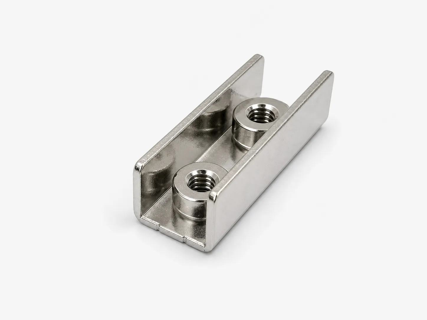
Stamped copper busbars, battery terminals and power connectors may look simple, yet their manufacturing risk sits at the interfaces. Holes must align with studs, formed legs must land at the correct height, contact pads must avoid damage or unwanted coating, and burrs must face away from sensitive areas. Those requirements need to be visible before tooling and production are priced.
This guide covers manufacturing and RFQ inputs for stamped copper parts in battery, energy-storage, charging and power assemblies. It does not calculate ampacity or promise system performance. The buyer specifies material and functional targets, then validates the part under its actual joint, temperature, load, insulation and assembly conditions.
Short answer: what to send for a copper busbar or terminal quote
Send a controlled 2D drawing, STEP/STP model when available, and a brief identifying the item as a busbar, battery terminal, connector, link or tab. Include revision, assembly context, prototype quantity, production quantity and annual volume so the supplier can review the tooling route.
Identify buyer-specified material, thickness, temper, datums, formed features, contact faces, burr direction, plating, joining interfaces, first-article checks and packaging. List any mating stud, fastener, insulator or gauge available for sample review.
- Provide controlled files, assembly context and any approved sample reference.
- State quantities, inspection records and packaging requirements before quotation.
Keep copper grade and temper under buyer control
Copper is not one interchangeable material. Grade, temper, hardness, thickness tolerance and supply condition affect forming, surface condition, springback and buyer calculations. Because designations vary by standard and market, cite the exact buyer-approved specification rather than a broad note such as pure copper.
The supplier may review availability and propose an alternative, but should not silently select a grade or temper. Define any substitution process and required material certificates, traceability or test records in the RFQ, including the governing method and acceptance value.
- Name specification, temper or hardness, thickness and surface condition.
- Separate mandatory requirements from alternatives needing written approval.
Define thickness, cross-section and geometry without an ampacity shortcut
Thickness, width, necks, openings and formed transitions affect blank nesting, support, material use, flatness and edge cleanup. Mark minimum functional widths and geometry that cannot change during DFM instead of applying one tight profile tolerance everywhere.
Do not infer current capacity from thickness alone. Performance also depends on material condition, joints, plating, fasteners, contact pressure, temperature, airflow, duty cycle and insulation. The buyer should release the geometry and validate the assembled system. The Copper Development Association's busbar tables have stated material, frequency, surface and temperature-rise conditions; a value from those tables is not a current rating for a stamped battery terminal. [2]
- Dimension functionally fixed necks, tabs, slots and transitions.
- Keep ampacity, temperature rise and fault approval in the buyer's test plan.
Control bends, holes, datums and flat contact areas
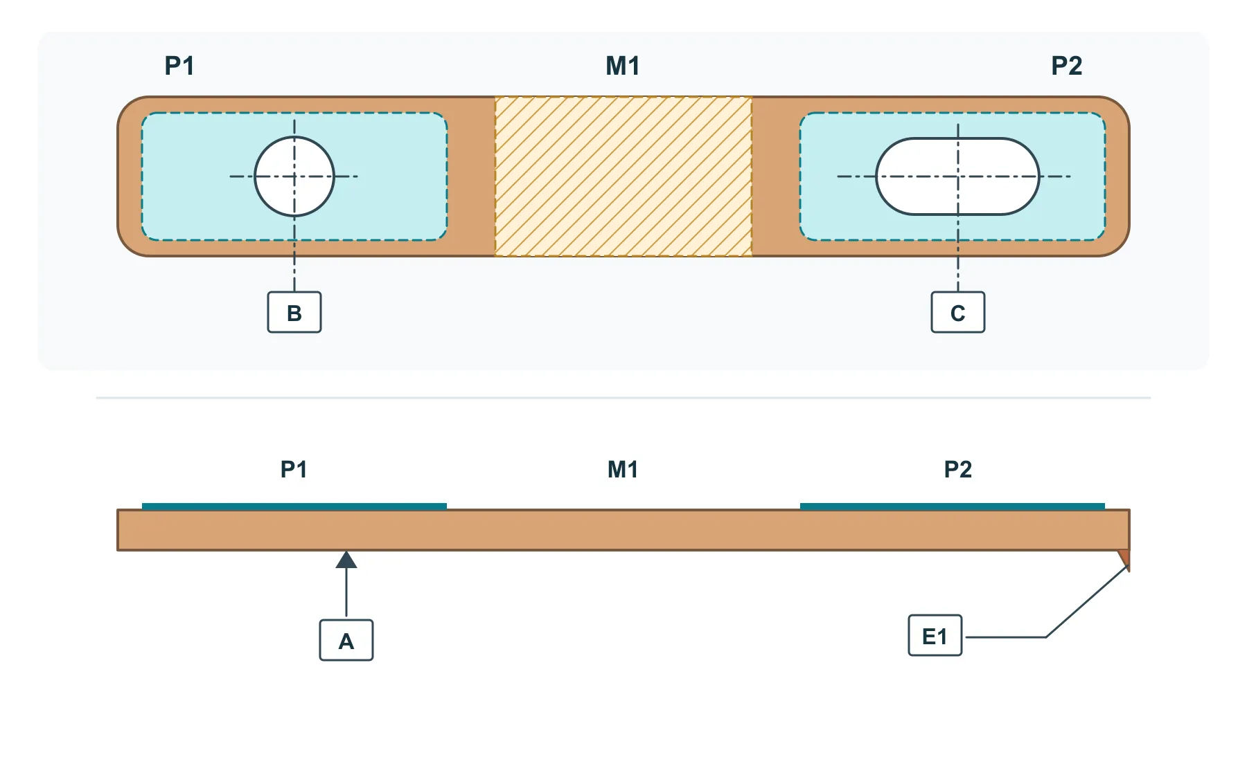
Locate holes and formed heights from the features that actually position the part. In this teaching example, A is the underside support face, B the round-hole axis and C the slot center plane. These are example locating references, not a complete geometric-tolerance specification. The drawing must define the actual datum features, tolerances and measurement setup.
Control surface flatness on the named contact area without a datum reference in the flatness callout. If two pads must share a height or face a mounting plane, specify that relationship separately using the appropriate dimensions or geometric control. A flat pad can still be tilted or at the wrong height. Record whether inspection is before or after plating and whether the part is free or restrained. [1]
- P1 / P2: outline the mating contact footprints and identify the other conductor and its finish.
- A / B / C: show what supports and locates the part; use these references for the required assembly relationships.
- E1: identify the edge facing insulation. The enlarged burr in the side view shows the side to discuss, not an allowable burr height; orientation alone does not replace an edge limit.
Show burr direction and acceptable edge condition
Blanking and piercing create rollover and burr sides. Edge orientation matters near insulation, cables, users, mating faces and automated assembly. Show the required smooth side or burr direction instead of relying on a general deburr note.
Define measurable limits only on functional edges. Heavy deburring can change profile or hole size, while tumbling can mark soft copper. The supplier should propose a compatible method and confirm it on first articles.
- Mark the side facing insulation, cables, users or mating surfaces.
- Protect contact pads from deburring media and handling marks.
Map plating, masking and contact zones on the drawing
Use the same zone IDs in the drawing, finish specification and inspection report. For the illustrated example, P1/P2 receive the specified contact finish and M1 is masked to remain unplated. This is one selective-plating layout, not a rule that every busbar needs a bare center. A contact zone may itself be plated; contact does not automatically mean bare copper.
A usable note states the finish system and underplate, thickness requirement and measurement locations, zone boundaries, permitted transition band and any rack marks. Define both faces, holes and edges so the finisher does not have to infer hidden coverage. Confirm the finished hole fit and contact condition on samples, including removal of masking residue.
- For P1/P2, write the mating part, finish specification, coating thickness and acceptance check beside the zone ID.
- For M1, state the required unplated extent and how the boundary is located; unresolved finish choices can be marked for review.
Describe joining and assembly interfaces
Busbars and terminals may be bolted, riveted, clinched, welded, brazed, soldered, crimped or overmolded. Identify the interface because holes, finish, flatness, access and contamination limits may depend on it. Provide mating components and acceptance criteria if secondary joining is quoted.
For bolted joints, identify fastener references while the buyer owns torque and joint qualification. For welded or brazed assemblies, state the process, fixture datums and inspection method. A correct loose part does not prove completed-joint performance.
- List mating conductors, fasteners, insulators and inserts by revision.
- Separate loose-part dimensions from post-joining assembly checks.
Build inspection around functional features and buyer validation
First articles should confirm material, thickness, datums, holes, formed height, contact flatness, burr direction, finish and appearance. Agree whether checks use standard instruments, CMM, fixture, gauge or mating assembly, and state part restraint where it changes the result.
Production inspection should follow risk and volume. Define sampling, critical characteristics, certificates and lot identification before release. The manufacturer verifies part conformance; the buyer validates ampacity, temperature rise, fault behavior, vibration, corrosion and insulation coordination.
- Link the inspection plan to the tooling and sample drawing revision.
- Keep system qualification separate from dimensional and finish records.
Protect copper parts in packaging and complete the RFQ checklist
Copper can scratch, dent, bend or stain during bulk handling. Flat busbars may rub, formed terminals can tangle, and contact pads can collect fingerprints or residue. Define cleanliness and handling in the quality plan, then approve packaging on samples.
Use trays, separators, sleeves, interleaving or sealed bags as needed. State units per pack, orientation, labels, lot separation, protective materials and whether packaging may touch contact zones. Align drawing, finish, inspection and packaging in one RFQ.
- RFQ: part revision, copper specification, geometry, quantities, tooling and finish.
- Approval: critical checks, certificates, traceability, packaging and system-test boundary.
| RFQ area | Manufacturing risk to review | Buyer input to provide |
|---|---|---|
| Copper material | Different grades and tempers form, mark and spring back differently | Exact specification, temper or hardness, thickness, substitution rule and required records |
| Flat profile and cross-section | Narrow necks, slots and local transitions affect stamping and material use | Critical widths, profile datums, thickness tolerance and no-change functional areas |
| Holes and formed geometry | Hole distortion, springback and accumulated bend relationships can affect assembly | Mating references, hole position, bend radius, formed height and free-state measurement notes |
| Contact flatness | Part stress and measurement restraint can change the reported result | Named contact area, flatness tolerance without a datum reference, inspection state; separate controls for pad height and orientation |
| Burr and edges | A burr can face insulation, cables, users or a mating surface | Burr direction, controlled edges, burr limit and approved deburring method |
| Plating and contact zones | Coverage and buildup can affect fit, joint faces and appearance | Finish standard, thickness, underplate, selective map, masking and required tests |
| Joining and inspection | Loose-part conformance does not establish finished-joint performance | Joining context, mating parts, critical checks, gauges, sample plan and buyer validation |
| Packaging and traceability | Soft copper can scratch, bend, stain, tangle or damage adjacent contact surfaces | Pack orientation, separators, cleanliness, lot labels, certificates and shipment quantity |