HARVLAND works from customer drawings to produce custom set-top box metal enclosures. For projects that need a metal housing with fewer finishing operations after forming, a prepainted sheet metal cover is an option to discuss. Start with the enclosure envelope, board layout and connectors, then define the finish, forming and assembly requirements.
A ventilated cover with a prefinished surface
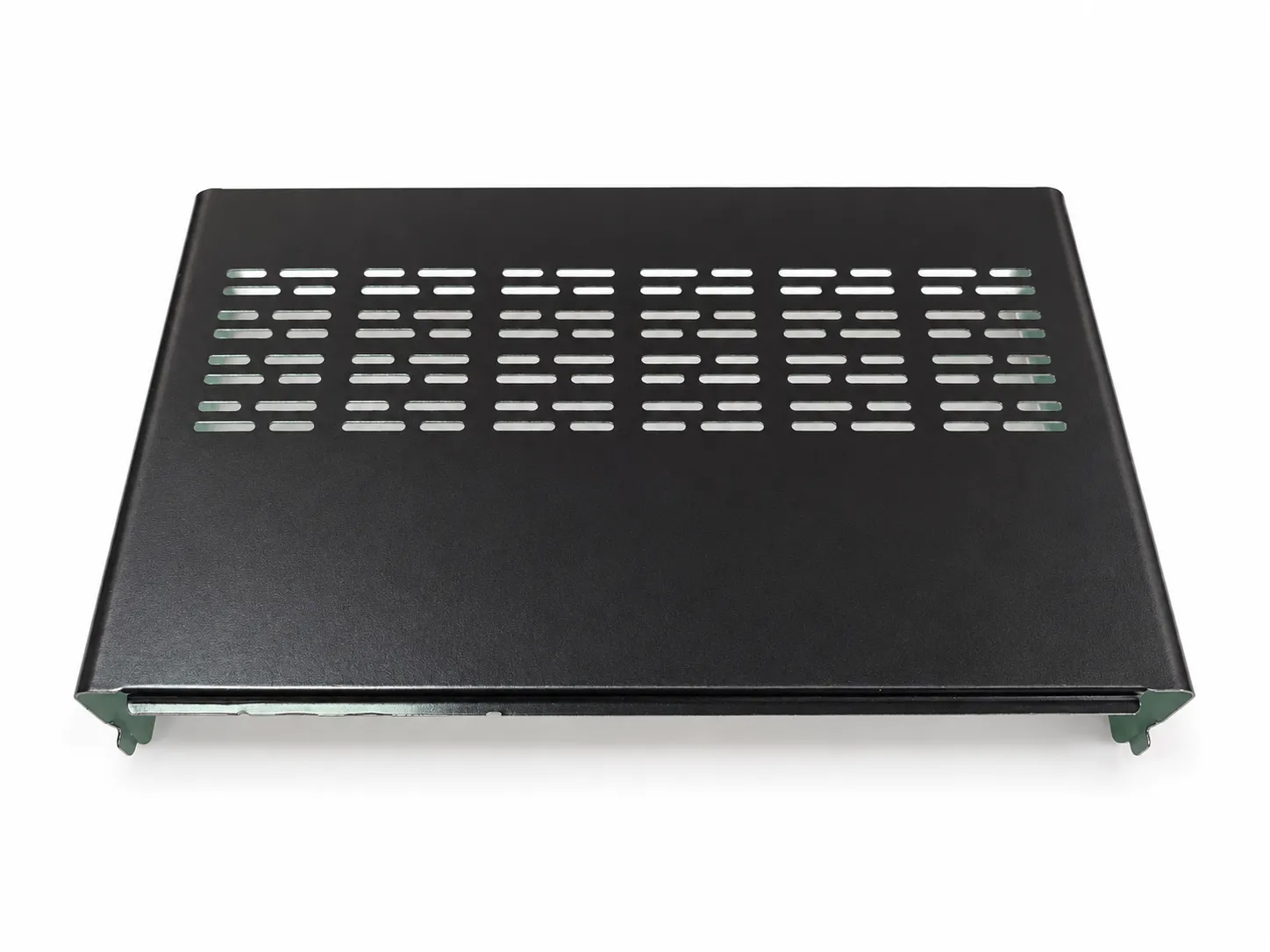
The illustrated cover has a black exterior and a green interior. Elongated ventilation slots run across the broad face and along both sides. The raised sides, edge returns and local attachment features provide a starting point for discussing the cover layout and its relationship with the rest of the enclosure.
Review the cover together with the base, front panel and circuit board. A useful drawing shows how the cover slides or lowers into place, how connectors align, and how the unit opens for servicing. Use the illustrated cover as a discussion reference; define each project's openings and joining details in its drawing and sample approval.
Why consider prepainted sheet for a set-top box enclosure?
The coating is already present when the sheet enters fabrication. The manufacturing route therefore needs to preserve the finished surface through forming. When the appearance is settled and the geometry suits the coating, this can remove the later whole-part coating operation and its associated handling steps.
Specify color, gloss and texture together, and distinguish the requirements for each face. Two black finishes can look quite different under the same light. A physical color standard or approved sample is more useful for appearance acceptance than a photograph alone.
For the material and process comparison, see prepainted metal for electronic enclosures .
What should be defined together?
| Requirement | Useful customer input | Drawing and sample review |
|---|---|---|
| Envelope and installation space | Overall dimensions, board outline, tallest components and mating base | Internal clearance, cover overlap and assembly direction |
| Connector openings | Actual connector positions, plug envelope and insertion direction | Datums, alignment and access for connection |
| Ventilation | Heat source locations, product orientation and nearby obstructions | Opening placement, edge condition and assembled thermal verification |
| Appearance | Color standard, gloss, texture and main visible faces | Coating at bends, scratching and batch appearance |
| Attachment and servicing | How the cover opens and the proposed fastening method | Assembly sequence, fit and repeated removal |
| Electrical contacts | Required grounding or shielding contact locations | Defined contact construction and electrical verification |
Place vents and cutouts around the assembled equipment
Slots provide passages for air exchange, but the number of slots does not establish cooling performance. The same cover on an open desk and inside a tight cabinet has different clearance around its openings. Specify the operating orientation and surrounding space, then check temperature rise on the assembled device.
Connector openings need more than the dimensions of the connector's metal shell. Plug bodies, finger access and board mounting position affect usability. For HDMI, USB, Ethernet, power or other openings, provide the dimensions and layout of the connectors actually used in the project.
Review the interior, folded edges and contact locations
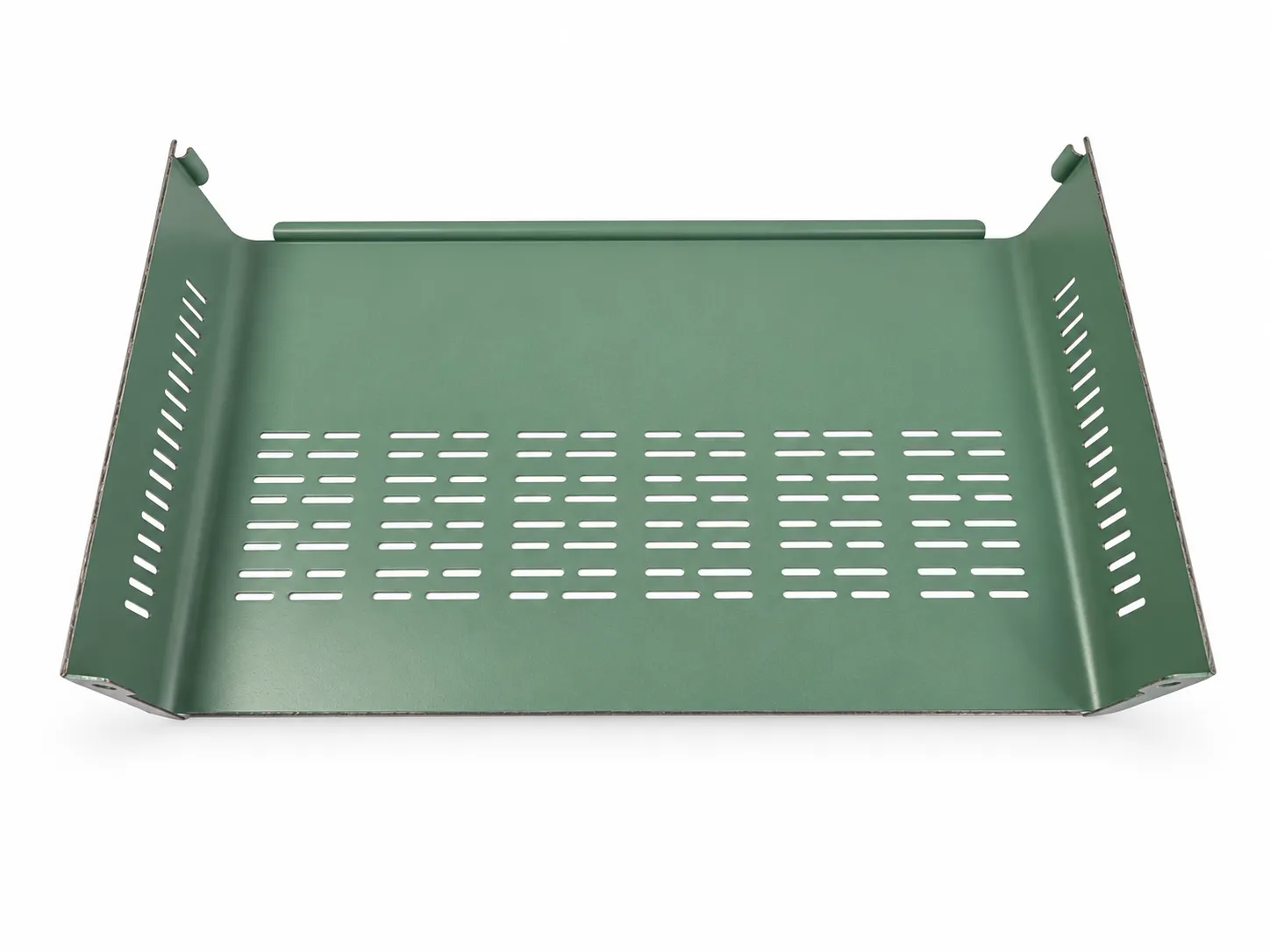
Visible faces need protection during fabrication and handling. Inside the unit, identify edges near cables, areas close to the board and locations that require metal contact. These annotations help define edge condition, clearance and joining requirements.
Where grounding or shielding continuity is required, specify the contact locations and acceptance criteria. A metal enclosure or a screw connection alone does not establish continuity. Vents, seams, panel joints and contact construction belong in the assembled product's EMC design and verification.
Start with a drawing, sketch or photograph
Send a drawing, sketch or sample photograph with the equipment's purpose, expected quantity, mating base and board dimensions. If material grade, thickness or finish is undecided, mark it as an open item so the structure and prepainted route can be discussed together.
Review fit, appearance, connector access and relevant functional requirements at the sample stage. Keep the approved drawing, material specification and appearance sample together as the production reference.