Camera brackets: match the device interface and mounting face
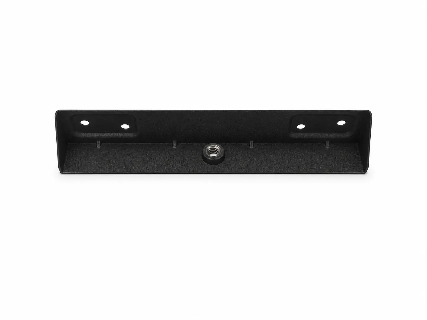
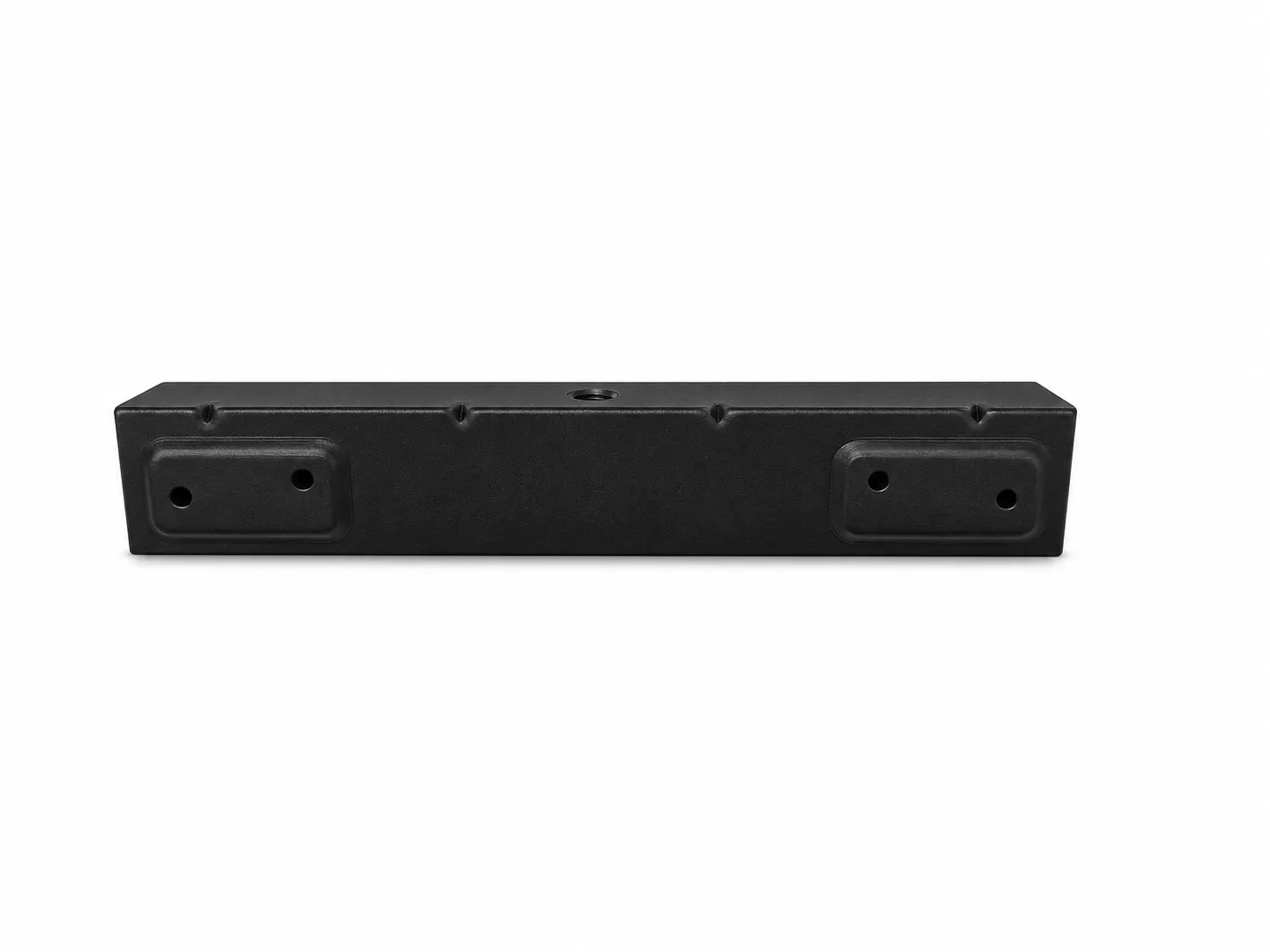
The black elongated camera bracket shown here has two formed faces, four mounting holes and a central internally threaded connection. Local formed features are visible near both ends. A custom version needs to relate the camera-side connection to the hole pattern on the mating mounting face.
Specify the central thread, required engagement and fastener length. A photograph of a threaded opening cannot establish compatibility with a particular camera. Dimension the four mounting holes from agreed datums, and identify which face points toward the device and which contacts the mating part.
Check flange height, the device envelope and access for assembly tools as well as hole alignment. If the camera must rotate or change direction, show its required movement range, lens field of view, connector position and cable exit. Trial-fit the sample with the intended device, fasteners and mounting face to check that installation does not obstruct viewing or connection access.
Describe the black appearance separately from the material and finish specification. Provide a color or appearance reference and identify threads or contact faces that need special treatment. Agree the substrate, finishing process and acceptance criteria for the project.
Perforated fire-protection brackets: define the installation and acceptance requirements
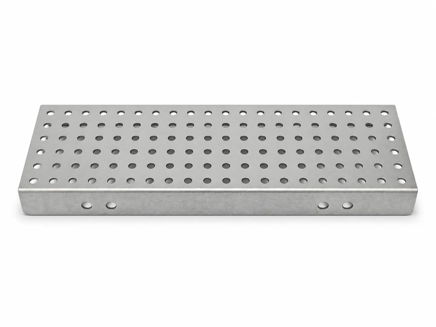
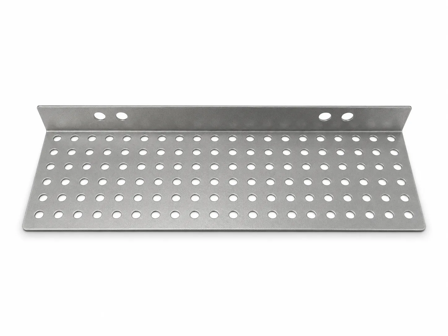
The silver-colored fire-protection bracket has a regular pattern of circular holes and a long formed flange with separate mounting holes. Start a custom requirement with an installation photograph or section sketch showing its location, spacing to adjacent components and the area it needs to cover or support.
Define hole diameter, center spacing, pattern and the material to retain around the edges. Distinguish areas where holes are permitted from areas that must remain solid. Match flange length, height, direction and mounting holes to the surrounding structure; a similar-looking part is not enough to establish interchangeability.
If the project requires ventilation, coverage, support or another function, identify the relevant area and acceptance conditions before reviewing the hole pattern and flange arrangement. The appearance or number of holes alone does not establish whether these requirements are met.
For projects with fire-performance requirements, provide the applicable equipment requirements, assembly arrangement and validation conditions. Verification needs to address the intended assembled configuration. A fire-resistance rating cannot be assigned from the name “fire-protection bracket” alone.
AV board brackets: align the fixings and allow space on both sides
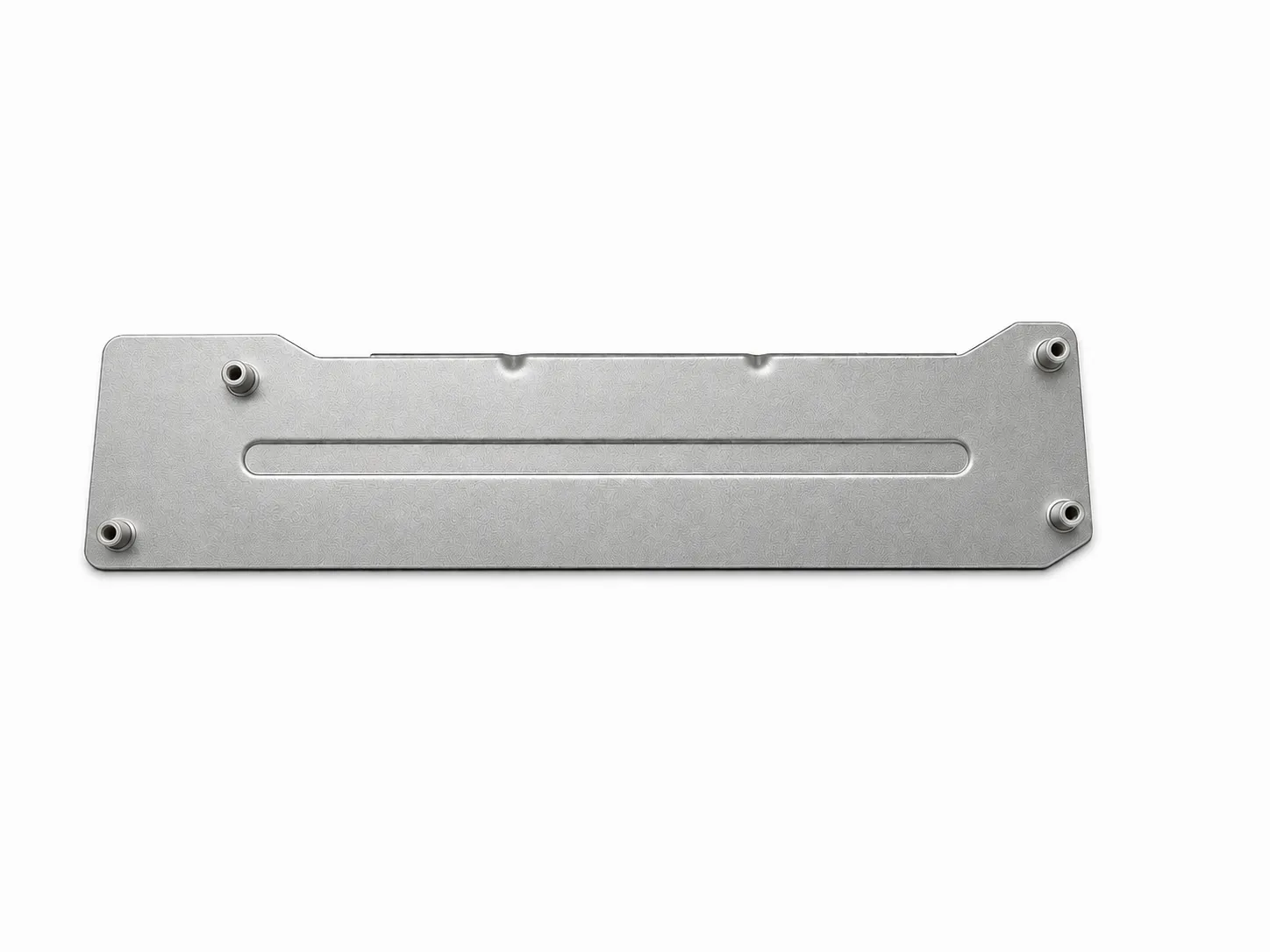
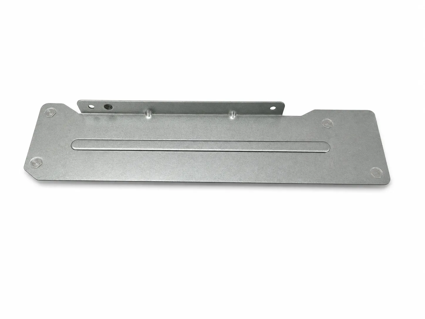
The silver-colored AV board bracket has an elongated profile, a long formed bead, a flange and four raised attachment features. Specify the board outline, mounting points and support height together, rather than matching only the outline of the metal plate.
Provide the AV board model or drawing revision and mark its fixing locations. Components on both sides of the board, solder tails, screw ends and the adjacent housing all affect available space. Identify locations requiring electrical isolation or a specified contact connection so the project requirements can be defined.
The long bead and flange occupy space on the two sides of the bracket. Review both faces and an assembly section to avoid contact between these features, the fasteners and board components. Include room to insert and remove connectors, route cables and use the intended assembly tools.
Define the height, hole or thread requirements and attachment method of the four raised features on the drawing. Use the actual board, connectors and fasteners during sample review to check alignment, clearance and assembly sequence. If several board revisions share a project, check each relevant version.
What should you provide for each bracket?
| Bracket | Information to provide first | Focus of sample review |
|---|---|---|
| Camera bracket | Device interface, thread requirements, mounting-face holes, device envelope and cable direction | Alignment and fastening, orientation, viewing and movement range, connector and tool access |
| Perforated fire-protection bracket | Installation location, coverage or support area, hole pattern, solid zones, flange and project acceptance conditions | Profile and holes, assembly clearance, flange direction and the agreed functional verification |
| AV board bracket | Board revision, fixing points, support height, components on both faces and connector space | Alignment, component and screw clearance, connector access and assembly sequence |
Match the material, finish and edges to the application
Specify the material grade, sheet thickness and surface treatment instead of relying on “black” or “silver.” If these details are not yet fixed, explain the operating environment, appearance requirements and contact with adjacent materials so the options can be discussed.
Mark edges that may contact cables, the board, operators or mating surfaces, and describe the required edge condition. Include protected threads, designated contact faces, cosmetic surfaces and packaging separation requirements so these operations are included in the quotation review.
From an assembly requirement to an approved sample
Describe the assembly problem
Send a drawing, sketch or photographs of the part and its installation location. Explain what it connects and what needs to change. A complete CAD model is not required to start the discussion.
Agree the quotation basis
Review datums, holes, flanges, attachment features, material and finish. Include sample quantities, anticipated production quantities and timing. List unresolved items for confirmation.
Check the intended assembly
Trial-fit the sample with the actual equipment or board, mating parts and fasteners. Check clearance, tool access and agreed functional requirements, then record the findings against the drawing or sample approval.
Fix the production revision
Confirm the drawing revision, approved sample, inspection items and packaging before arranging production. Recheck affected interfaces when the equipment or board design changes.