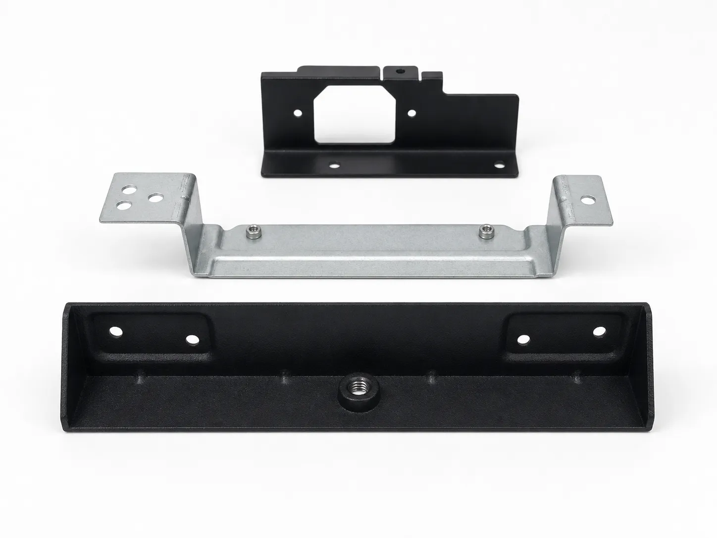
Custom metal brackets look simple, but the drawing connects structural load, mating geometry, forming behavior, installed hardware, coating and inspection. A bracket that fits the CAD envelope can still crack at a bend, distort a nearby hole, block installation tooling or stack up out of position after coating.
Treat the drawing as a manufacturing and assembly specification. Define the functional datums, load direction, mating parts and environment first; then select the geometry, material, thickness and process. The supplier can review manufacturability, but the buyer or responsible engineer must validate load, fatigue, safety factor and system-level performance.
Start with the load path, datums and environment
Before choosing an L, U or Z profile, identify what the bracket must locate, support or restrain. Show the load direction, mounting datums, mating faces, fastener access, clearance envelope and any vibration, corrosion, temperature or electrical-grounding requirement that affects the part.
Dimension critical holes and formed faces from functional datums instead of chaining every feature from a cut edge. Include an assembly view when adjacent components control fit. A design-for-manufacturing (DFM) review can identify production risk, but load capacity, fatigue life and safety factor remain application-specific engineering decisions.
Choose L, U, Z or reinforced geometry
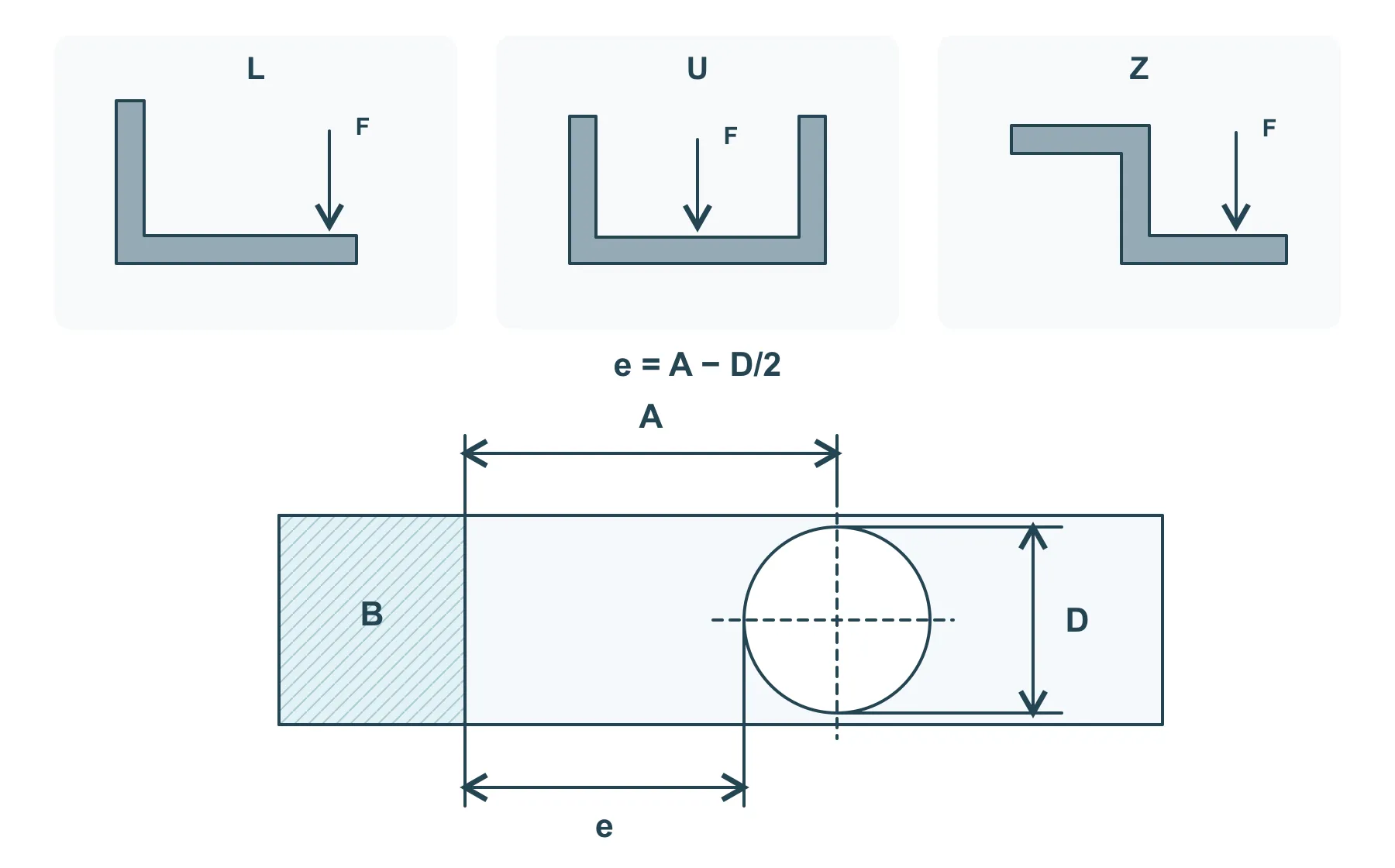
An L profile turns between perpendicular mounting faces; a U profile surrounds a component; a Z profile offsets two mounting planes. The arrows in the sketch show example loads to discuss with the design engineer. Moving a load farther from its support increases the bending moment for the same perpendicular force. Shape alone gives no load rating: include the support locations, load direction and unsupported span in the assembly review.
Choose the simplest shape that gives the required load path and tool access. Returns, ribs and gussets can increase section stiffness, but they also add forming stations, tolerance interactions or joining work. The comparison table below highlights the main DFM risk for each family.
Select material and thickness without guessing
Material grade, temper and thickness affect stiffness, yield behavior, corrosion, springback, bend radius, tooling force and finish compatibility. Low-carbon steel is economical and formable, galvanized steel adds coating considerations, stainless steel improves corrosion resistance but may need more forming allowance, and aluminum reduces weight while changing stiffness and bend behavior.
Do not choose thickness from a generic bracket chart alone. Use the actual load case and mounting span, then check whether a return flange, rib, bead, gusset or shorter unsupported leg can add stiffness more efficiently than a heavier gauge. Confirm any allowed material substitution because a nominally similar alloy or temper can bend differently.
Design bends, reliefs, holes and installed hardware together
Bends and nearby features share the same material, tooling and operation sequence. A radius near one material thickness can be an early concept for some ductile low-carbon steels, but it is not a universal minimum; stainless grades, harder tempers and some aluminum conditions may need a larger radius. Grain direction, burrs and surface condition can also change crack risk.
Define the dimension's endpoints before comparing a spacing rule. In the sketch, A is the perpendicular distance from a round hole center to the bend tangent on the same flat flange; D is the hole diameter; e is the clear distance from the hole edge to that tangent. Therefore e = A − D/2. The tangent is where the straight flange meets the curved bend, not the theoretical sharp corner or the bend centerline.
Teaching example: A = 8 mm and D = 4 mm give e = 8 − 4/2 = 6 mm. This describes the geometry; it is not a recommended minimum. For slots or irregular cutouts, measure the actual nearest boundary. A hole near a bend needs review against material, thickness, tool opening, forming sequence and permitted distortion. Move it, add a suitable relief or evaluate making the hole after forming when its position is critical.
Measure hole-to-edge distance from the hole edge to the finished cut or pierced edge, not from the hole center. The required ligament depends on hole diameter, material, edge condition, load direction and whether the feature is laser-cut, punched or stamped. Treat generic thickness multiples only as screening values, and confirm load-bearing or position-critical holes in the DFM review.
WorldAutoSteel explains how a bend puts the outer surface in tension and the inner surface in compression. Its steel examples show why material condition and bend-radius-to-thickness ratio matter; they do not provide one minimum radius for every alloy. Use the material-specific forming assessment and the intended tooling when releasing the bracket.
- Add bend relief where adjacent flanges would tear, overlap or distort, and size it for the actual process.
- Check minimum flange length and tool access before locking short returns, closed corners or deep channels.
- Show burr direction, bend direction and cosmetic faces when they affect assembly or appearance.
- Specify PEM hardware, rivet nuts, weld nuts or studs with installation side, sequence and tool-clearance space.
- Control position-critical holes and mounting faces in the formed state from functional datums.
Choose fabrication, single-operation stamping or progressive tooling
Laser cutting or punching followed by press-brake forming is usually the flexible route for prototypes, lower quantities, larger brackets and designs that may change. Simple or single-operation tooling can make sense for stable repeated features without committing to a full progressive die. Progressive stamping becomes attractive when stable geometry and recurring demand can amortize tooling and benefit from faster, repeatable production.
There is no universal quantity at which stamping wins. Ask for quantity-band pricing that separates prototype or fabrication cost, production tooling, sample approval, secondary hardware, finish and recurring unit cost. Compare total program cost and revision risk, not only the lowest piece price.
Control finish, tolerance stack and inspection
Finish is part of the dimensional and assembly plan. Zinc plating, powder coating, passivation or anodizing can change appearance, friction, electrical contact and fit at holes, slots, threads or mating faces. State the finish specification, color or texture where relevant, and identify masked, conductive, grounding, threaded and no-coating areas.
Avoid applying the tightest tolerance to every dimension. Identify functional datums and critical formed relationships, then agree how angle, profile, hole position and overall formed size will be inspected. A first-article or sample report should reference the controlled revision and record any approved deviation.
- Identify cosmetic faces, allowable forming marks and burr-sensitive edges.
- Define which dimensions are checked after forming and after coating.
- Call out required material, finish and inspection records before quotation.
- Specify part separation, protective packaging and label or traceability needs for finished brackets.
Prepare a complete custom bracket RFQ package
Send both a revision-controlled PDF drawing and a STEP/STP model so dimensions, tolerances and notes can be checked against the formed geometry. Include assembly context and identify what is fixed versus open to DFM adjustment. A complete package lets the supplier compare fabrication and stamping without hiding assumptions in the quote.
- Controlled 2D drawing revision plus STEP/STP part and assembly geometry.
- Material grade, temper or condition, thickness and permitted alternatives.
- Order quantity bands, annual demand and expected program life.
- Load direction, mating parts, mounting datums and installation-tool access.
- Critical formed dimensions, tolerances, bend direction, burr direction and inspection basis.
- PEM hardware, riveting, welding or other secondary operations and their sequence.
- Finish, coating thickness where relevant, cosmetic faces, masking and conductive areas.
- Sample or FAI expectations, required records, packaging and target timing.
| Bracket type | Best used for | Main DFM risk | Typical route |
|---|---|---|---|
| L-bracket / angle | Perpendicular mounting faces | Flange length, angle and hole shift | Press-brake forming or stamping |
| U-bracket / channel | Cradling and three-sided support | Inside width, parallelism and tool access | Press brake or staged stamping |
| Z-bracket / offset | Mounting across two planes | Two-bend tolerance stack and sequence | Press brake or stamping |
| Flat mounting plate | Mounting patterns without bends | Flatness, edge distance and burr direction | Laser cutting, punching or blanking |
| Gusset / reinforcement | Increasing joint stiffness | Load transfer, joining access and distortion | Fabricated or stamped |