HARVLAND works from customer drawings to produce custom WiFi router metal enclosures. Discuss the housing around the circuit board, connectors, antenna arrangement and installation space. This black trapezoidal housing provides a concrete reference for combining a distinctive profile with port openings, panel markings and cover assembly.
Define the trapezoidal profile in the drawing
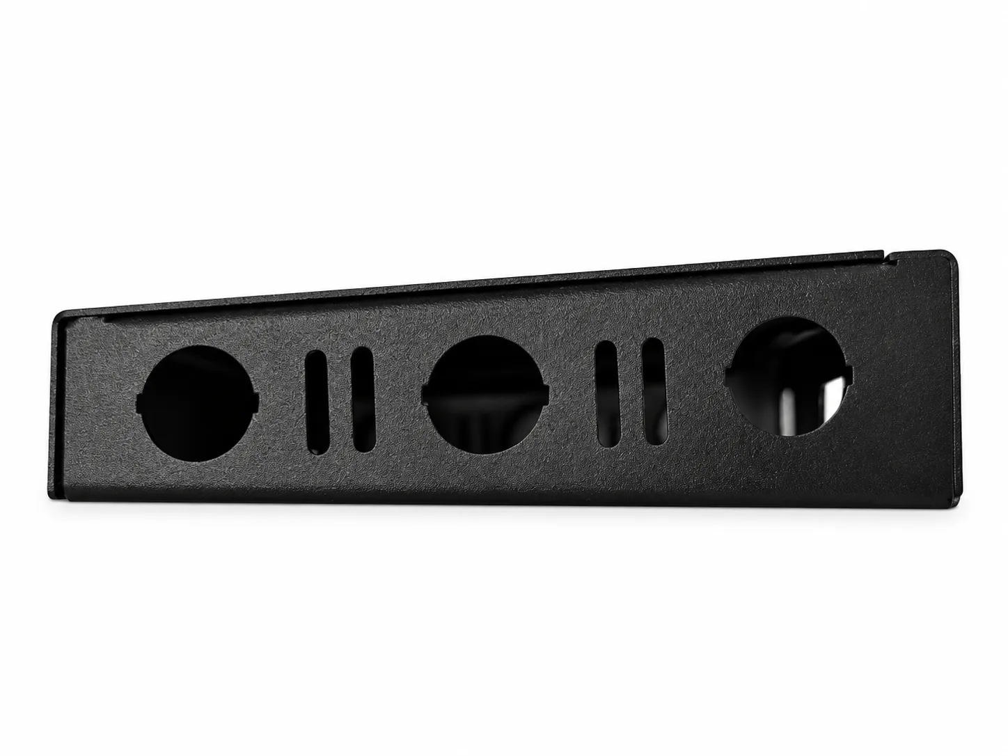
In this view, the upper edge rises toward the right, with a shorter left end and a taller right end. Three round openings and four narrow slots are visible. A fabrication drawing needs to define that profile explicitly; a maximum length, width and height alone does not describe the sloping geometry.
Provide heights at relevant positions, the slope or angle, and the mating relationship with the base and cover. If only a styling sketch is available, identify the taper you want to retain, then review it against the board and components. Check internal clearance by location, especially near the lower end, connectors, heatsinks and cables.
Align LAN, Reset and other openings with the actual components
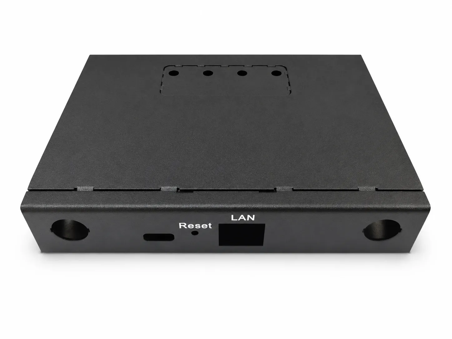
The interface panel shows LAN and Reset markings alongside rectangular, round and elongated openings. Specify each opening from the actual connector, button or cable fitting. A count of round holes does not establish the antenna count or the device's network features.
An Ethernet opening needs room for the plug body and latch operation as well as connector alignment. A reset access hole must match the button position and intended operation. Specify power, USB and other openings from the customer's board. Relating interface positions and board mounting holes to common datums makes assembly review more useful than estimating each opening separately.
Review the metal housing and antenna together
Include antenna placement before freezing the housing. An ordinary board-mounted antenna surrounded by metal, or with metal inside its required clearance area, can lose wireless performance. Follow the selected antenna or module's integration requirements; ordinary panel holes alone do not establish an adequate RF path.
An external antenna is one option to discuss. Define its bulkhead opening, retention, internal connector and cable space from the selected components. An internal antenna requires an RF review of placement, non-metal areas and nearby structure. Validate either approach with the final housing, cables and installation orientation. Define the intended use of the sample's openings in the project drawing.
What should be reviewed together?
| Item | Useful input | Sample review |
|---|---|---|
| Trapezoidal appearance | Styling sketch, local heights, slope and installation orientation | Profile, low-end clearance and mating parts |
| Board installation | Board outline, mounting holes, tallest components and keepout areas | Datums, component clearance and cable paths |
| Ports and markings | Connector drawings, layout, text and reading orientation | Plug access, Reset operation and label alignment |
| Antenna | Placement requirements for the selected antenna, connector and module | Retention, clearance, cable space and assembled RF verification |
| Heat and contacts | Heat sources, thermal parts, grounding or shielding contacts | Actual contact construction, temperature rise and electrical checks |
| Finish and servicing | Color and texture reference, visible faces and maintenance method | Assembly scuffing, cover fit and repeated removal |
Black texture, folded edges and cover fit
The sample has a black textured appearance. Use a physical reference to agree color, gloss and texture, and identify the main visible faces. Specify substrate, thickness and finishing process separately in the material and manufacturing requirements.
Review cover edges, seams and local attachment features alongside the assembly sequence. Where a cover slides into place, check for interference with connectors and cables and for rubbing against finished surfaces. Define any conductive contacts explicitly; metal construction or a screw alone does not establish reliable contact.
To compare a prepainted route, read the guide to prepainted metal for electronic enclosures and assess it against the router housing's geometry. A black finish alone does not identify how this sample was coated.
Move from an appearance idea to an agreed sample
Start an enquiry with a photograph, sketch or existing housing. Include the equipment's purpose, expected quantity, the trapezoidal profile you want to retain and the proposed board, port and antenna arrangement. Mark undecided material, thickness or finish as open items.
Review appearance, board installation, port operation, cover removal and cable space together at the sample stage. The assembled equipment then needs its thermal, wireless and relevant electrical verification. Keep the enclosure drawing, material requirements, panel markings and approved sample at the same revision.
See custom sheet metal enclosures for broader housing requirements, or the network equipment chassis RFQ guide for project inputs.