A network equipment enclosure RFQ should let a manufacturer understand what the chassis holds, how it mounts, where air and cables move, what finish is visible, and how samples will be approved. For custom sheet metal projects, those details usually affect quote accuracy more than outside size alone.
Start with the assembly interfaces that can change the quote or prevent the equipment from fitting. A marked-up assembly view is often more useful than a long list of product names: it shows what must align, what must stay clear and which parts will be supplied together.
Short answer: what to include in the RFQ
For a network switch chassis, server chassis or custom network equipment enclosure, send drawings plus a short written brief. The brief should state the equipment type, mounting method, material, finish, annual quantity, target sample quantity, inspection points and any compliance documents the buyer needs.
The most useful RFQ package also identifies the features that can fail silently: port alignment, vent patterns, fan openings, rack ears, rail interfaces, PEM inserts, standoffs, removable covers, grounding contact zones, label locations and packaging surfaces.
- Core files: 2D drawings, STEP/STP assembly files and DXF/DWG flats if available.
- Core product notes: network switch, router, CPE, mini PC, storage, server, GPU server or other equipment type.
- Core manufacturing notes: material grade, sheet thickness, finish, visible faces, inserts, welding, riveting and marking.
- Core approval notes: sample quantity, first-article dimensions, cosmetic criteria, RoHS/REACH records and packaging needs.
Why product context matters for chassis manufacturers
A general sheet metal enclosure can often be quoted from size, material, thickness and finish. A network or server chassis needs more context because the metalwork interacts with electronics layout, connectors, airflow direction, rack mounting, cable access and maintenance.
If that context is missing, server chassis manufacturers may quote the visible shell while missing cost drivers such as rear I/O alignment, perforation density, removable top covers, drive or power module access, grounding tabs, painted contact zones or protective packaging.
Mark six interfaces on one assembly view
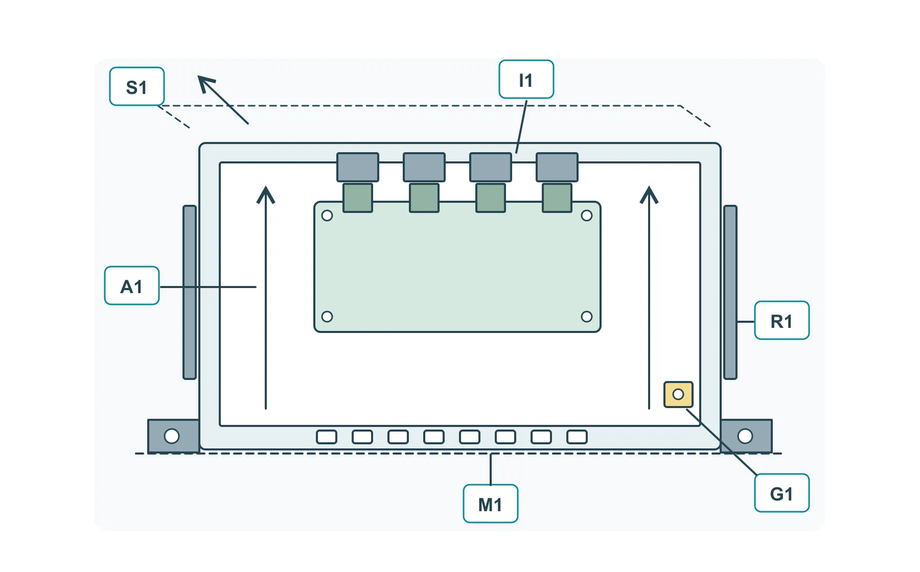
This sketch is a teaching layout for a chassis with a removable lid. Use the M1, I1, R1, A1, G1 and S1 labels in an RFQ note sheet, and replace the layout with your actual assembly. It does not define a rack standard, airflow result or certified grounding arrangement.
For each label, record the controlling drawing or mating-part revision, who supplies the part and how the sample will be checked. The table below shows six entries to adapt. If a rail model, board revision or contact treatment is still undecided, name the missing input and the person responsible for resolving it before sample release.
Define the equipment family and quote scope
For example, an RFQ can include the formed base, removable lid, mounting ears, specified inserts and finish, while identifying rails, fans and the board as buyer-supplied items. State whether these arrive for trial assembly or remain outside the delivery scope. Assign dimensional inspection and system thermal, EMC and electrical-safety validation to named project parties before sample approval.
- Part-only quote: formed panels, covers, brackets or trays supplied separately.
- Chassis assembly quote: sheet metal parts plus inserts, rivets, hinges, captive screws or welded hardware.
- Enclosure kit quote: metal parts, finish, labels, basic hardware and buyer-specified packaging.
- Project review quote: DFM feedback before sample release, then revised pricing after drawing changes.
Mechanical envelope, rack size and mounting
The mechanical envelope should show outside size, internal clearance, board mounting points, connector positions, cover direction and how the unit mounts in the final product or rack.
Rackmount products need extra clarity: rack unit height, ear or bracket geometry, rail interface if used, front-panel alignment and rear I/O access. If the design is not tied to a standard rack, say so, because that changes how the supplier reviews tolerance stack-up and assembly fit.
- 2D drawings plus STEP/STP files for the full enclosure or chassis assembly.
- Board, connector, fan, power supply and cable clearance references when available.
- Mounting ears, wall brackets, feet, slots, standoffs or rail interface details.
- Critical dimensions for panel fit, port alignment, rack fit and removable cover access.
I/O, airflow, EMI and grounding notes
Connector cutouts, LED windows, power entry, antenna openings, vent slots, fan holes and perforated areas should be visible in the drawing package. These features affect manufacturability, appearance, burr direction, structural stiffness and post-finish edge quality.
For EMI or grounding, avoid vague statements such as shielded enclosure unless the target has been defined. Instead, mark conductive contact areas, masked paint zones, grounding points, gasket locations or required review items. Tested EMI effectiveness or thermal performance should only be claimed after project-specific validation.
- Call out intake, exhaust, fan, filter or louver locations on the drawing.
- Mark grounding tabs, bare metal contact areas and paint masking zones.
- Keep EMI gaskets, finger stock or conductive finish requirements visible in the RFQ.
- Separate buyer-specified performance requirements from supplier DFM suggestions.
Material, thickness, finish and visible faces
Material choice affects strength, weight, corrosion resistance, grounding, appearance and forming risk. Cold-rolled or galvanized steel is common for strong sheet metal server chassis parts, stainless steel fits harsher environments, and aluminum is useful when weight, appearance or heat spreading matters.
Finish should be planned before quote release. Powder coating can provide durable color on visible steel chassis, anodizing fits many aluminum housings, and plating or masked bare zones may be needed around grounding or sliding contact features.
- State preferred material grade, thickness and acceptable substitutes.
- Define visible faces, texture, color, gloss, silkscreen or laser marking requirements.
- Mark masked, threaded, grounded or sliding areas where coating thickness matters.
- Include RoHS, REACH or material certificate needs when documentation is required.
Hardware, assembly and service access
Network and server chassis often include hardware that changes the manufacturing route: PEM nuts, standoffs, rivets, hinges, captive screws, welded studs, labels, light pipes or separate brackets. These details should be visible in the RFQ rather than added after pricing.
Service access matters too. Removable covers, front panels, rear panels and internal trays should be designed so assembly and maintenance do not require unnecessary disassembly or hidden fastener access.
- List PEM inserts, standoffs, rivets, weld nuts, tapped holes and screw types.
- Show which covers are removable and which panels are fixed.
- Define label, silkscreen, logo or serial marking locations.
- Clarify whether the supplier quotes only metal parts or a simple assembled chassis.
Sampling, inspection and release control
Before mass production, request samples or first articles so fit, finish, assembly and inspection assumptions can be checked against the drawing. For chassis projects, sample review should include port alignment, cover fit, insert position, finish appearance, grounding contact areas and packaging protection.
Inspection records do not need to be excessive, but they should match the risk of the part. Critical dimensions, cosmetic surfaces, grounding zones and hardware placement are usually more important than measuring every non-critical bend.
- Ask the supplier to confirm sample lead time separately from repeat production lead time.
- Mark critical-to-fit dimensions for ports, boards, rails, covers and bracket holes.
- Define acceptable cosmetic surfaces before powder coating, anodizing, plating or brushing.
- Keep drawing revisions, approved samples and inspection records tied to the same release level.
Final RFQ checklist for network and server chassis
A complete RFQ does not have to answer every engineering question, but it should make the highest-risk assumptions visible before the supplier quotes tooling, samples or production. The goal is a quote that engineering, purchasing and quality teams can all review without guessing what is included.
- Equipment type: network switch, server, mini PC, CPE router, storage device, GPU server or compute device.
- Drawing package: 2D drawing, STEP/STP assembly, DXF/DWG flats if available.
- Mechanical inputs: rack size, mounting, board and connector references, service access.
- Manufacturing inputs: material, thickness, finish, inserts, welding, riveting and marking.
- Approval inputs: sample quantity, inspection points, compliance records, cosmetic criteria and packaging needs.
| Drawing label | What to attach or specify | What to check on the sample |
|---|---|---|
| M1 · Rack mounting | Rack or mounting drawing revision, front mounting plane, ear holes and permitted envelope | Fit to the specified mounting fixture; verify hole locations from the agreed references |
| I1 · Board and I/O | Board revision, standoff heights, connector envelopes and plug/cable clearance | Fit the mating board or gauge; check port alignment and connector insertion space |
| R1 · Rails | Rail manufacturer/model, mounting drawing and supply/installation responsibility | Install the specified rails and check engagement, travel and interference; agree load testing separately |
| A1 · Air path | Intake/exhaust direction, fans, filters and cable keep-out zones; identify who supplies them | Check openings and obstructions against drawings; system team validates temperatures and airflow |
| G1 · Bonding contact | Contact location/area, finish or masking note, hardware and electrical acceptance requirement | Inspect contact treatment and assembly; agreed electrical test verifies bonding, not appearance alone |
| S1 · Service access | Cover removal direction, captive hardware and tool/cable clearance envelope | Remove and refit the cover with mating parts present; check access and retained hardware |