Review the disc, center hole and plastic rim together. Select rim material, hardness requirements and retention around the mating surface and operating environment. Appearance alone does not establish sealing or vibration-damping performance.
Two related sets of requirements
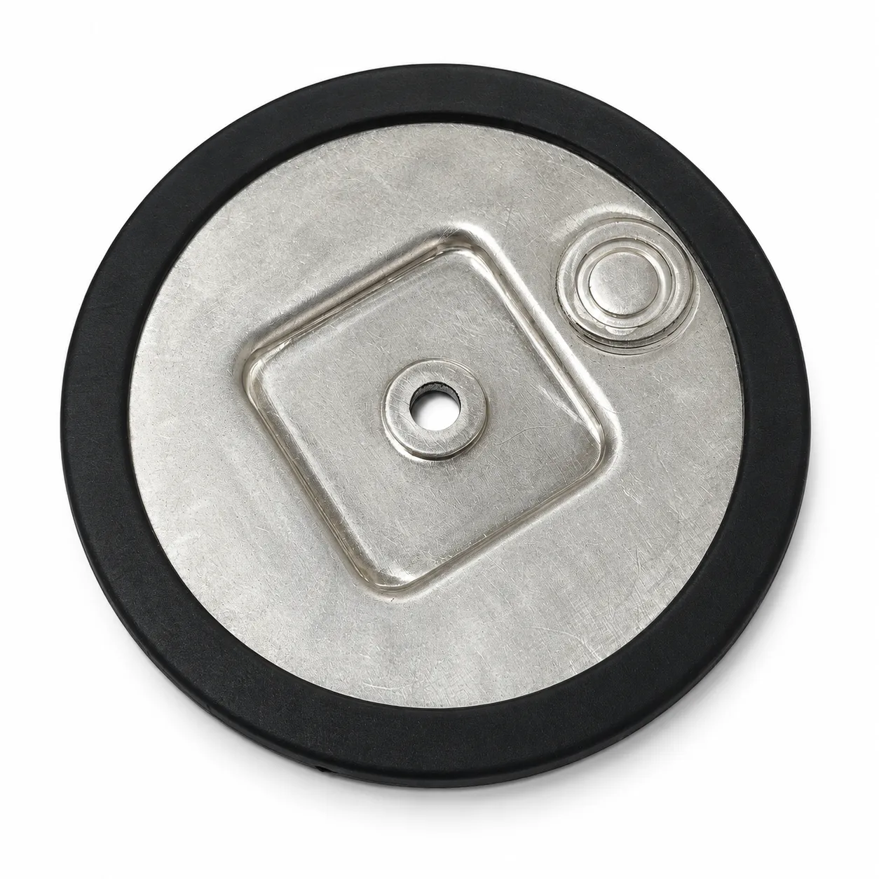
The sample shows a circular metal plate, a center through-hole, a rounded-square formed contour and a smaller circular feature near the edge. A black plastic component surrounds the perimeter. Photos of both faces help explain the forming direction and available space.
The descriptive name “metal disc with a plastic rim” is suitable for presentation. A cover, support or other mechanism project needs its actual mating drawing; a circular outline alone does not identify a wheel, diaphragm or equipment-specific part.
Use shared assembly datums
Where the center hole locates or secures the part, define its relationship to the outer edge and formed surfaces. Correct hole position alone does not ensure the installed height or perimeter clearance is suitable.
Mark the mounting face, center hole, contact areas and clearance zones on an assembly view. If flatness, runout or loaded shape matters, provide the operating conditions and inspection method before assigning dimensional or geometric requirements.
Choose the rim around its contact function
A rim can be designed around edge coverage, handling contact or assembly fit. Describe what it touches, sustained compression, removal needs, temperature and exposure. Hardness is only one part of material selection.
The rim and metal may be formed separately and assembled, or another joining route may suit the design. Review the actual structure and materials before choosing the process. A photograph does not establish overmolding, insert molding or adhesive bonding. Define verification conditions for any sealing, wear or damping requirement.
Sample the metal and plastic to one assembly requirement
HARVLAND manufactures plastic parts in-house and can discuss the disc and rim as a coordinated project. Begin with an assembly sketch showing overall diameter, mounting position, mating surfaces and quantities.
Alongside the metal drawing, provide installed-rim dimensions and appearance requirements. Sample approval should check forming and hole position, rim seating, mating clearance and the intended operation. Agree the delivery condition for the project.