Start with the metal part you need to order
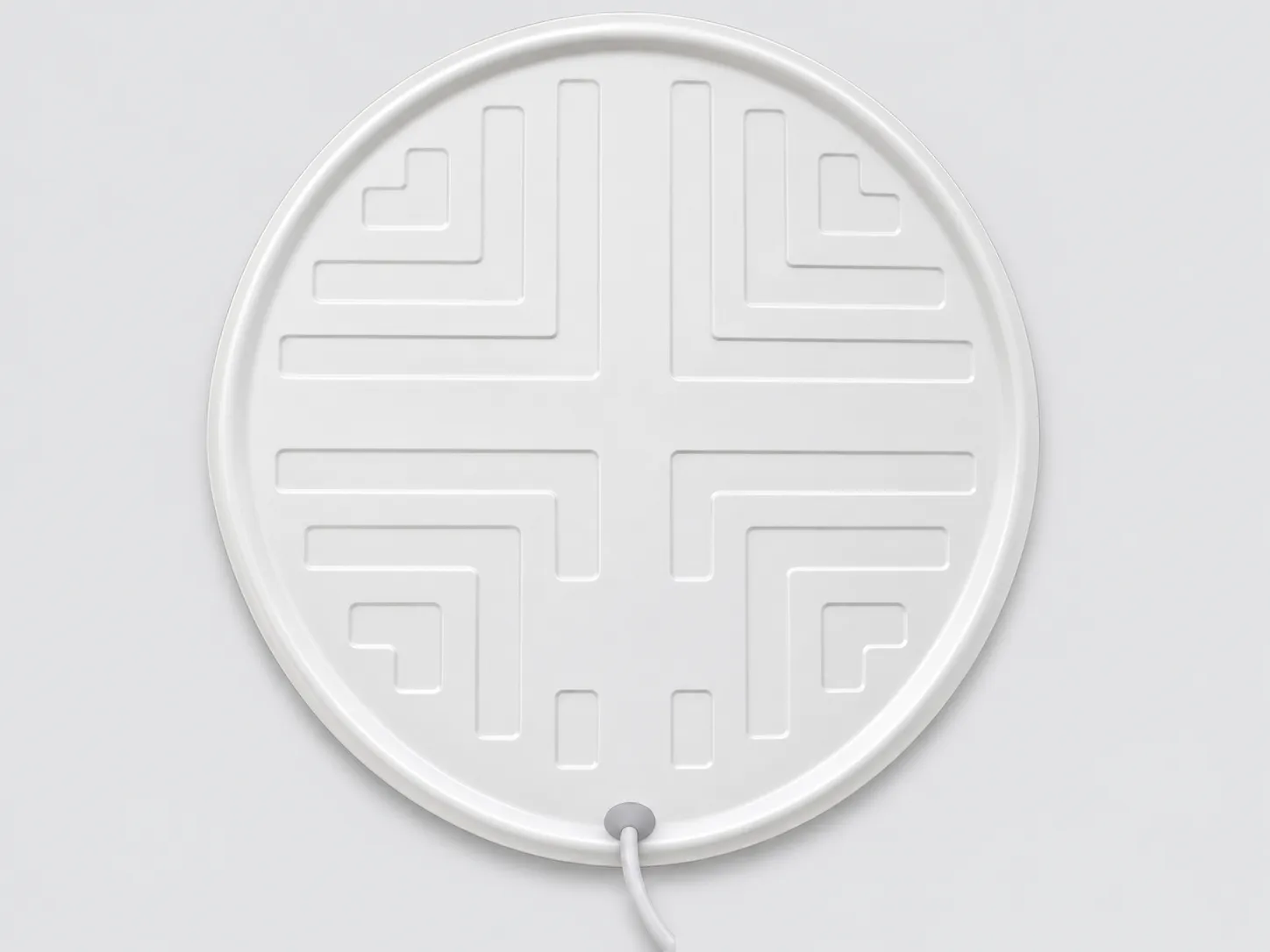
The round shell shown here has a shallow pan form, a white surface, a formed perimeter and an embossed panel pattern. A cable passes through a fitted piece near the edge. These features provide a useful starting point for discussing a custom light housing, but the supply drawing should show exactly which components belong in the order.
| Reference configuration | Specification |
|---|---|
| Material description | Color-coated sheet; base metal grade to be specified |
| Sheet thickness | 0.5 mm |
| Diameter | 265.24 mm |
| Appearance and form | White circular shallow shell with an embossed panel and formed rim |
Use these dimensions as the starting configuration. For production, agree the dimension locations, tolerances and mating details in the drawing.
For a metal-shell order, identify the shell separately from the LED modules, wiring, cable-entry fittings and any light-transmitting cover. If accessories are required, list them and provide the relevant component details. This makes it clear which interfaces need to be checked and what the finished delivery should contain.
Define the rim with the part it must fit
The circular edge is an assembly feature, so show both its profile and its relationship to the adjoining part. Start with the overall diameter and pan depth, then identify the seating surface, edge height and any overlap with a cover or mounting component.
For example, a cover that fits around the outside of a rim needs a different drawing detail from one that sits inside it. A section through the assembled edge explains that difference more clearly than a single top-view diameter. Mark where contact is intended and where clearance is needed.
If your design uses clips, screws or other retention features, provide their locations and the mating parts. Check the sample in the intended assembly, including the access needed to fit or remove those components. Do not copy an assumed attachment detail from a similar-looking lamp.
Coordinate the embossed panel and internal mounting areas
The stepped panel pattern and the flat areas between it should be reviewed alongside the internal component layout. Show which way each formed feature faces, its position and its section profile. Keep the drawing of the outside appearance consistent with the space required inside the shell.
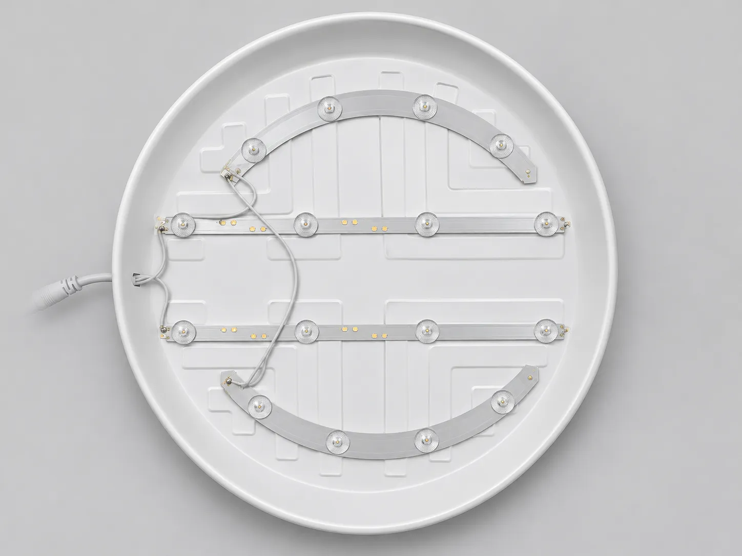
Where a light module or another component needs to sit against the panel, mark that contact area. Identify the attachment method and any surface that must remain clear. This lets the review address whether an embossed feature, fastener or cable route occupies the same space as the component.
If the panel pattern is being changed, supply the component layout as well as the preferred appearance. The sample check should cover the finished panel and the installed parts together, rather than approving only a photograph of the outer face.
Specify the cable entry as an assembled detail
Show the opening location, the direction in which the cable leaves the housing and the fitting intended for that opening. Supply the cable dimensions and fitting drawing or part reference where available. A hole dimension by itself does not define how the cable and fitting will sit in the metal.
Mark any edge that could contact the cable, and describe the intended edge treatment or protective fitting. If cable retention, sealing or an electrical connection is part of the design, include the corresponding assembly requirements and validation plan. Confirm those functions with the finished lighting assembly.
Agree on material and white appearance separately
The reference configuration is specified as color-coated sheet, 0.5 mm thick. The base metal grade and coating specification still need to be defined for production; the white appearance alone does not identify them. For another configuration, put the required material and sheet thickness on the quotation drawing. If these choices are still open, describe the installation environment, visible faces and assembly requirements so the options can be discussed.
For appearance approval, provide a physical reference or agreed color specification, and describe the required gloss and texture. Identify which faces will be visible after installation and any locations where marks are unacceptable. Compare the finished sample under agreed viewing conditions, particularly when the housing must match another visible component.
What to send for a round light-housing quotation
| Part detail | What to provide | What to check on the sample |
|---|---|---|
| Circular outline and pan depth | Dimensioned views, edge section and any overall space limit | Profile and depth against the agreed drawing |
| Rim and cover interface | Mating cover or mounting-part drawing, seating location and intended clearances | Seating, retention and installation access |
| Embossed panel | Pattern layout, feature direction and section details | Formed geometry and clearance to internal components |
| Internal attachment | Component layout, contact areas and attachment method | Position and seating of the intended components |
| Cable entry | Opening position, cable details and fitting reference | Fit, cable route and any specified protection or retention |
| Material and appearance | Material and thickness, finish requirements and visible faces | Drawing requirements and the agreed appearance sample |
| Quantity and delivery scope | Expected order quantities, required accessories and packing needs | Agreed contents and protection of the finished part |
If you are starting from a used or damaged sample, point out bent edges and other areas that should not be reproduced. Include undamaged mating parts or dimensioned sketches where possible. A restored product image can explain the intended appearance; the production drawing still needs the dimensions and interfaces that control fit.
Approve the sample in the condition that matters
Before approving a sample, agree which dimensions are checked on the free part and which are checked after assembly. Show the locating surfaces and fastening conditions for assembly checks. Record any appearance requirements after the specified finish has been applied.
Use the intended cover, internal components and cable fitting for the relevant fit checks. If the project has thermal, electrical or ingress-protection requirements, include them in the complete lighting product's validation plan. Keep those requirements distinct from the dimensional and appearance acceptance of the metal shell.