HARVLAND reviews drawing-based requirements for custom metal board brackets and shield covers used in conference displays, interactive flat panels and commercial display projects. Send a part drawing, board layout or photos of an existing sample, and explain where it mounts and where cables, connectors or conductive contacts need space. These details support discussion of the structure and quotation.
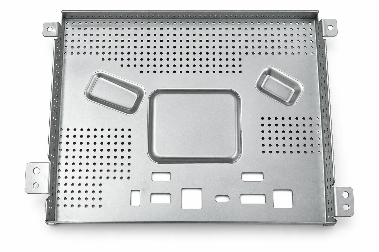
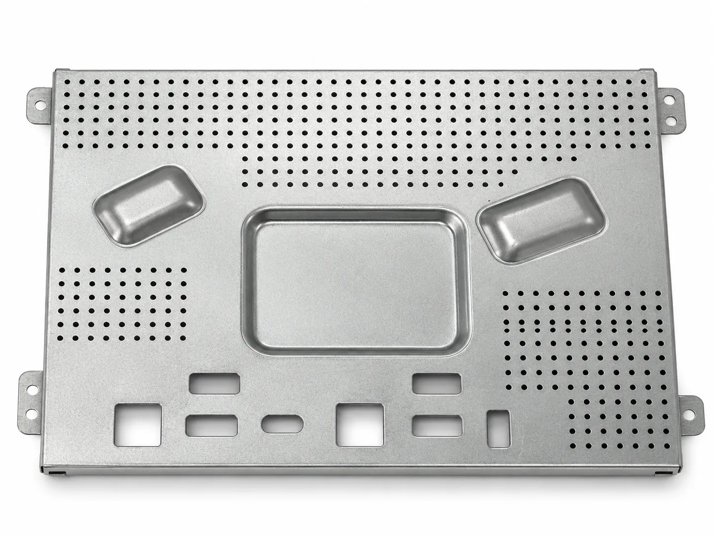
The illustrated part is used at an internal board bracket / shield-cover position in a conference display. Its shallow tray has perimeter flanges, four external mounting tabs, several round-hole fields, interface cutouts, one large rectangular formed feature and two smaller diagonal features. Each feature needs to follow the board and equipment layout.
Define the mounting and shielding requirements separately
A board bracket addresses fixing, positioning and available space. When it also forms part of a shield, conductive connections to adjacent metalwork, openings and seams need attention. Identify which functions the part must provide and which performance requirements will be established through equipment design and validation.
Mark the board-facing side, rear-housing attachments, board support or fastening method and service-removal direction on the assembly drawing. Include any separate standoffs or supporting components. External mounting tabs should not automatically be treated as PCB fastening holes.
Mounting tabs and flanges: check the formed part, not only the flat pattern
External mounting tabs connect the main panel to the equipment structure. Choose the locating surface first, then define hole diameters, hole spacing and each tab's height relative to that surface. Hole spacing on a flat pattern does not fully describe how a bent part will seat.
Trial-fit samples to the actual mating structure. Check that screws align without forcing, tabs seat properly and tightening does not visibly twist the panel. Tightening the screws harder should not be used to conceal incorrect hole positions or formed heights.
| Feature | Information to provide | Sample check |
|---|---|---|
| Mounting tabs and holes | Mating holes, fasteners, locating surface and formed heights | Alignment, seating and tool access at each attachment |
| Perimeter flanges | Direction, finished height and rear-housing clearance | Profile, interference and distortion after fastening |
| Board-adjacent areas | Board outline, component heights and support method | Clearance to components, solder joints, screws and cables |
| Connector cutouts | Connector model, position and plug-body dimensions | Insertion and removal with connectors and cables installed |
| Conductive contacts | Mating part, surface condition and agreed check method | Contact checks under the equipment plan; separate EMC validation |
Review formed features for stiffness and board clearance together
Ribs, embossments and other local formed features change a sheet's cross-section and can be considered as ways to increase local bending stiffness. The three features shown have different sizes and orientations. Their depth, radii and positions need to suit the sheet material, forming process and assembly.
A formed feature occupies space on one side of the panel. Supply the component, housing and cable layouts on both sides, then check clearance at the highest feature and at screw ends. Do not assume an embossed area is a board support or allow it to bear on components or solder joints without an agreed contact design.
If more stiffness is required, discuss the formed area, flanges or sheet thickness and compare their effects on weight, space and manufacture. Confirm the chosen design by dimensional inspection and trial assembly; load or vibration targets require the project's separate validation.
Coordinate ventilation and shielding around the complete equipment
Ventilation holes provide air passages, but cooling also depends on heat-source positions, airflow paths, fans and the space inside the rear housing. Review the hole fields alongside the actual heat sources and inlet / outlet locations. Another board, foam or a close-fitting housing can block them. A larger open area does not necessarily lower equipment temperature rise.
When the part contributes to electromagnetic shielding, apertures and seams also affect electromagnetic coupling. Give the equipment EMC engineer the hole dimensions, layout, seam contacts and target frequency range together. Neither a universal hole diameter nor the apparent density of a pattern guarantees shielding effectiveness.
If thermal and EMC needs conflict, discuss revised hole zones, compartment layouts or suitable conductive connections and validate the assembled design. A perforated sheet and an engineered honeycomb shielding vent have different structures; the vent's performance data cannot simply be assigned to the sheet.
Connector cutouts need alignment, plug access and cable space
A connector opening needs more than a position taken from the PCB. Check connector height above the board, the location of the formed panel, plug-body size and cable movement. HDMI, USB and Ethernet are possible interface examples only; use the drawings of the connectors selected for your project to define the actual openings.
Fit the real board, connectors and cables during sample evaluation. Check full insertion, latch access and cable bends near flanges. Define edge treatment and inspection requirements wherever an opening can touch a cable or a service technician.
Conference flat-panel mainboards, interactive display controller boards and other commercial display boards can need different openings and clearances even when their housings look similar. Supply the specific board number and revision. Screen diagonal alone is insufficient to define an internal bracket.
Select material, finish and production route for the actual function and batches
Specify base material, sheet thickness and surface treatment together. A silver appearance does not identify galvanized steel, stainless steel or aluminum. Compare candidate materials against forming, stiffness, weight, protection and conductive-contact requirements before agreeing the grade and supply condition.
If contact with the rear housing or another metal part must be conductive, mark that area on the drawing. Define acceptable surface treatments, any masking and the assembly check method. Mechanical fastening alone does not establish the required electrical connection.
Dense perforations and local formed features require a considered sequence of piercing, forming, bending and any leveling. Compare laser cutting or CNC punching plus bending with dedicated stamping tooling against the geometry, sample quantities, repeat batches and likelihood of revision. Flat cutting and bending alone do not replace a local embossing operation.
| Item | What to agree | Keep the comparison consistent |
|---|---|---|
| Material and thickness | Grade, thickness and supplied condition | The same structure, weight and functional targets |
| Finish | Protection, appearance, contact areas and masking | The same conductive areas and delivery condition |
| Production route | Piercing, local forming, bending, leveling and inspection | The same drawing revision and finished-part acceptance |
| Quantities and costs | Samples, batch size, credible repeat orders and tooling charges | Compare total cost at quantities you actually expect to buy |
| Packaging | Protect formed areas, mounting tabs and surfaces | The same transport and incoming-inspection requirements |
Start an RFQ with a drawing, board layout or sample photos
You do not need every material and tolerance decision settled before starting a discussion. Send the part drawing, sketch or photos you have. Mark the board, housing, connectors and areas needing conductive contact, and explain the assembly problems you want to resolve. Identify undecided items as to be confirmed.
If CAD is available, include a finished-part 2D drawing, 3D model and mating-part information. With an existing sample, add views of both sides, key dimensions and its installed position. A quotation also needs sample and batch quantities, delivery destination and the schedule you would like to discuss.
Record sample results separately for dimensions and appearance, mounting fit, board and connector clearances, cable protection and any specified contact checks. Validate temperature rise, EMC and other equipment targets separately using an agreed configuration and method. Recheck affected requirements after board, cutout or finish changes.