A T-CON metal plate with bridge-like features
This T-CON metal plate has two raised features with round details on their surfaces and narrow openings along the sides. It illustrates the appearance of a local raised platform transitioning to the surrounding plate at both ends. The photographs have been retouched to show the overall part.
For an engineer or buyer, the important starting point is the interface: does a surface need to support a mating part, or must a hole align with another component? Is clearance required underneath? These answers affect height, hole position and inspection.
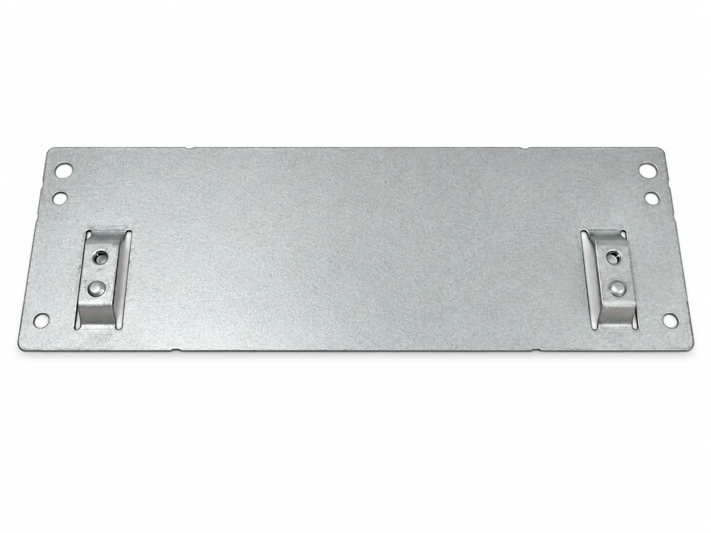
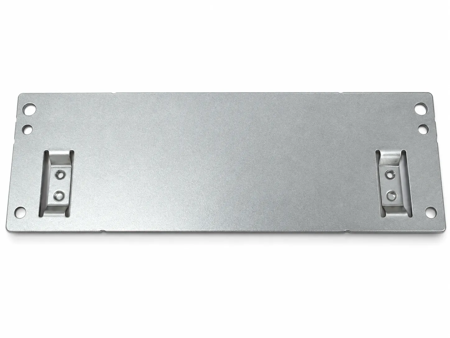
How does a bridge differ from a single-ended lance?
A single-ended lance cuts part of a contour and retains one root. A bridge is usually cut on two sides and keeps both ends attached. Each end has a transition where bending and the surrounding sheet's deformation must be considered. Tooling can combine cutting and forming in one action; the actual number of operations depends on the part and tooling.
| Consideration | Single-ended lance | Bridge lance |
|---|---|---|
| Connection to sheet | One retained root | Both ends retained |
| Form | Raised tongue | Raised bridge surface and two transitions |
| Review | Root cracking, angle and springback | Both roots, bridge height, slit ends and position |
| Possible use | Positioning, clip or guide | Guide, positioning, cable tie or other local feature |
These applications are design possibilities. The intended assembly defines the function; a formed shape alone does not establish load capacity or clip life.
What happens during forming?
The slit edges undergo shear as the tooling cuts; the two transitions bend as the bridge rises. Elastic recovery after unloading can change the final height. Cut-end shape, root width, material condition and form height affect local deformation. When increasing height, check for cracks, excessive thinning and distortion of the surrounding sheet.
Where a bridge has a hole or another local detail, review its size and position together with the final bridge attitude. Whether to pierce before forming or use a later operation depends on the hole's assembly function, tool access and sample results.
What should the drawing specify?
| Information | Why it matters |
|---|---|
| Bridge height and datum | Define which parent surface and bridge surface establish the measurement, and permitted tilt. |
| Bridge length, width and transitions | Define the mating surface, root space and available tooling. |
| Slit and end geometry | Make cutting, root transitions and burr requirements clear. |
| Hole size and position | Dimension functional holes from assembly datums in the formed state. |
| Nearby clearance | Account for adjacent holes, edges and access for the upper and lower tools. |
| Material, thickness and surface | Material condition and coatings affect forming and appearance. |
Identify the height, mounting face, hole or spacing that controls assembly, then agree the inspection datum and method. Avoid giving every feature the same tight tolerance without a functional reason.
Compare manufacturing routes
A dedicated lance-and-form tool or a forming tool in a punch press can produce local bridges. For stable geometry and recurring demand, compare a stamping-tool route against the complete plate outline, holes and quantities. While a design is changing, discuss other routes that achieve the same assembly requirements.
Compare tooling, sample quantity, expected production volume, revision cost and secondary operations alongside unit price. A single local forming tool is not automatically a complete progressive die.
What should be checked on samples? / Preparing an enquiry
- Bridge height and orientation from the agreed reference.
- Roots and slit ends for cracks, scoring, excessive deformation and functional burrs.
- Functional hole size and position, plus local distortion of the surrounding plate.
- Clearance under the bridge and access for assembly tools or adjacent cables.
- Appearance, allowable forming marks, finish and records required by the drawing.
Agree acceptance criteria and measurement methods for the project. A photograph does not establish fit, strength or life.
Send a drawing, 3D model, sketch or sample photo, with bridge height, critical holes, mating parts and expected quantity. If the drawing is not complete, describe what the feature needs to do, the available space and dimensions that affect assembly.