What does “angle bracket” describe?
This guide focuses on a bent sheet metal connector with two mounting faces. The terms right-angle bracket, L bracket and corner brace can describe overlapping product families. They do not define a complete specification: check the actual drawing and connection arrangement.
The illustrated part has two faces, four round holes and a local reinforcing feature at the bend. It is an example for discussing interfaces, not a universal replacement bracket. Distinguish a finished connector from angle-section stock that still needs cutting or machining.
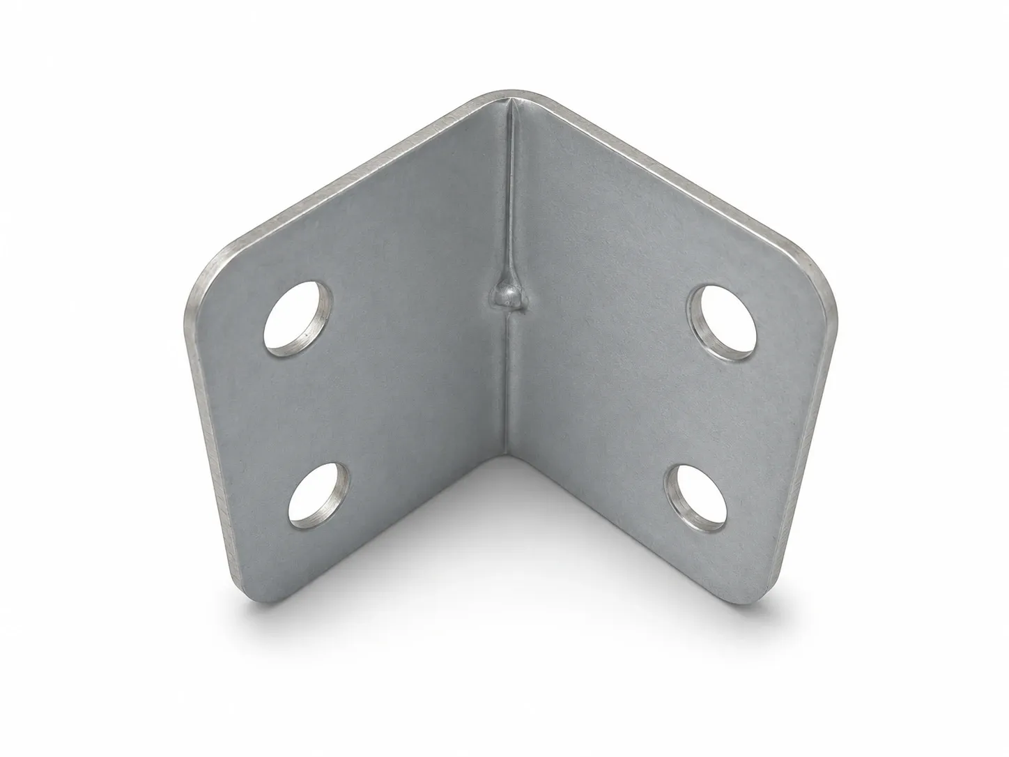
Choose around the connection, not the product name
A furniture corner connection, an equipment-panel fixing and a shelf support need different assembly information. Similar-looking brackets may use different fasteners and contact areas. Identify what each face attaches to and which features locate the parts.
For each application, check the actual mating parts and fasteners. A small corner fitting should not be treated as equivalent to a shelf bracket with a diagonal brace.
| Application to discuss | Information to supply | Interface to review |
|---|---|---|
| Cabinet or furniture corner | Panel material, thickness, contact area and screw arrangement | Leg coverage, hole pattern and screw-head clearance |
| Equipment panel to base | Mating drawing, fixed face and assembly sequence | Hole datums, angle and tool access |
| Shelf or small support connection | Support locations, service load and point of application | Bracket, fasteners and attached parts as a complete assembly |
| Frame corner | Frame section, joining method and space limits | Interface dimensions and any dedicated connector features |
Specify both legs and the finished mounting geometry
Define each leg length, strip width, thickness and finished angle. Identify whether dimensions refer to an inside surface, outside envelope or assembly datum. Equal-looking legs in a photograph do not establish equal drawing dimensions.
State the spaces that matter: one leg may need to stay inside a panel edge while the other must clear a cable or adjacent component. Specify those limits before selecting a catalogue size or asking for a custom profile.
Match the holes to the fastener arrangement
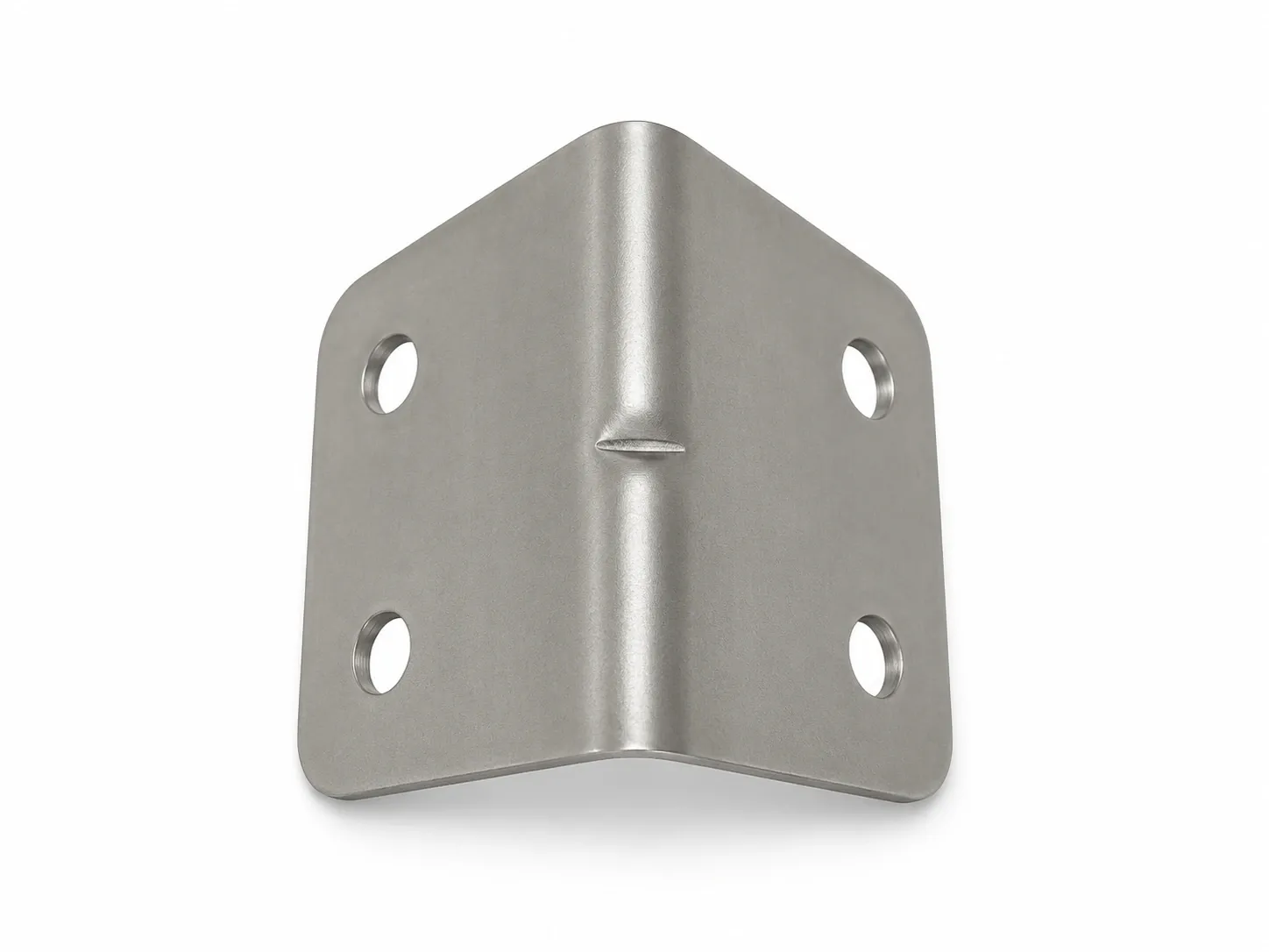
The reference sample has four round through holes, two per face. The number of holes does not establish their diameter, spacing or screw size. Locate them from agreed datums and compare them with the mating part.
If a flush screw head is required, define the head style, hole-mouth profile and seating requirement together. A bright ring in a photo does not prove a countersink. Countersunk angle brackets are a separate specification choice, not an assumed feature of this sample.
If installation needs adjustment, discuss a slotted-hole version and define its direction, usable adjustment and final clamping requirements. Round, countersunk and slotted holes should be selected for the connection rather than treated as interchangeable descriptions.
Keep material and finish separate
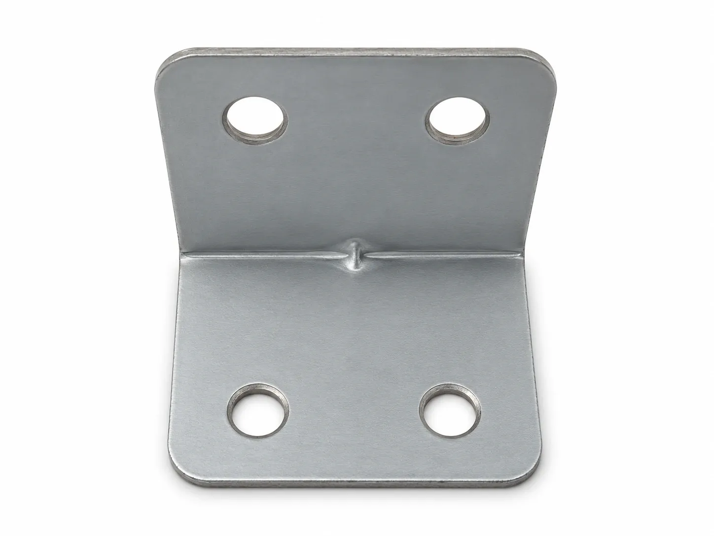
Specify the required grade and supplied condition when ordering a stainless steel angle bracket. A silver appearance alone does not identify stainless steel, its grade or a protective coating. Connect the drawing requirements with the agreed material documentation and acceptance method.
Describe moisture exposure, visible surfaces and contact with other materials where relevant. If the grade or finish is undecided, identify the service conditions for review instead of guessing from a retail photograph.
Reinforcement does not establish a load rating
A thicker section or a formed rib is a design feature, not a complete load specification. Provide the bracket geometry, material, fasteners, attached parts, mounting method, load location and permitted movement when discussing performance.
Review the installed assembly under agreed conditions. For the local feature at the bend, see the sheet metal gusset and reinforcing-rib guide. That guide addresses the rib; this one addresses selection of the corner connector.
When should you discuss a custom angle bracket?
A custom version is worth reviewing when available sizes cannot meet the hole pattern, unequal leg lengths, clearance or material requirements. Mark the interfaces that must remain fixed and the dimensions that may change.
Send a drawing, sketch or sample photo with the connection arrangement and expected quantity. Explain whether the request is to reproduce a sample or change its holes, profile or installation space. Tooling, price and delivery arrangements can then be assessed against the agreed scope.
Send the corner-connection requirements
Share what the bracket connects, where it is fixed and which dimensions must remain unchanged. For broader forming considerations, use the metal bracket design guide. For sourcing, see custom metal brackets or send drawings for review.