What is a sheet metal gusset at a bend?
A formed sheet metal gusset is a local reinforcement made in the parent sheet at a bend. It changes the corner geometry without introducing a separate joining plate. It differs from a welded gusset, which is an additional part attached to the bracket.
The bracket shown here has two mounting faces, four round holes and one local reinforcing feature at the bend. The outside and inside views help locate that feature; a section view on the drawing should define its final shape.
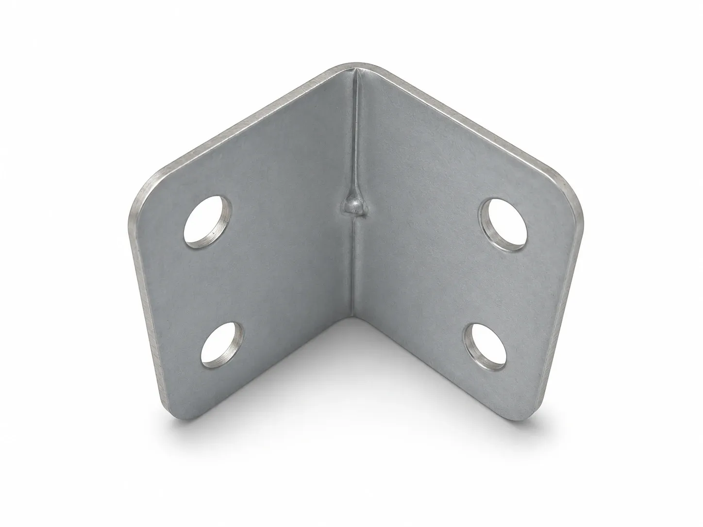
Specify the gusset around the mounting interface
Start by identifying the faces that must sit against mating parts. Then show the space available around the bend, including fasteners and installation tools. A useful drawing describes the reinforcement in relation to those interfaces, rather than simply asking for a stronger corner.
CAD parameters such as depth, width and radius describe a gusset; they do not establish manufacturing approval. Agree the finished geometry and review the forming route together. Do not turn a nominal rib depth into a universal rule for every alloy and sheet thickness.
| Drawing item | What to define | Review question |
|---|---|---|
| Material and thickness | Grade, supplied condition, thickness and applicable tolerance | What inputs will forming and structural checks use? |
| Gusset position | Location from an agreed edge, centerline or datum | Does the feature remain clear of the mating assembly? |
| Profile | Width, depth, extent and transition radii in a section or detail view | Is the intended geometry unambiguous? |
| Direction | Raised and recessed sides | Which side may occupy assembly space? |
| Finished interfaces | Bend angle, hole locations and contact areas | Can the bracket be fitted and tightened as intended? |
| Acceptance conditions | Mounting method, load location and allowed deflection | What must the sample demonstrate? |
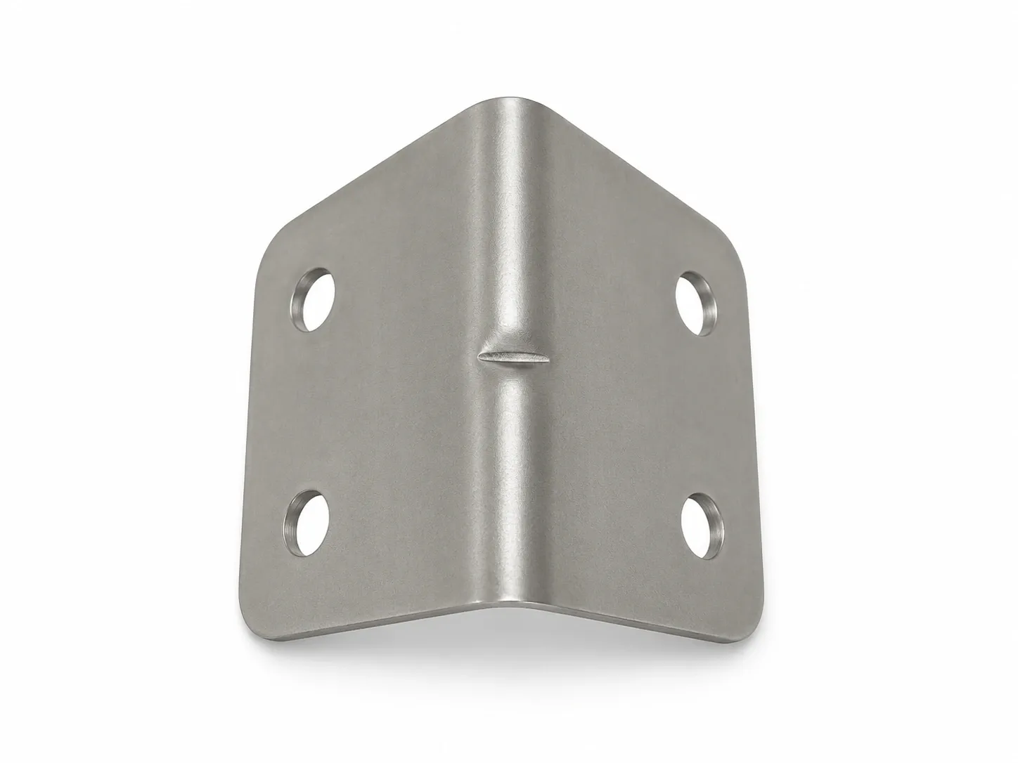
Stiffness is not a load rating
A formed gusset can increase local rigidity at the bend. Whether that improvement meets the application depends on the complete bracket and its mounting conditions. For this geometry, a useful review question is whether movement between the two faces affects the connected part.
Ask for the load direction, the point where it is applied and the permitted movement. The presence of a rib alone does not establish an allowable load or a percentage improvement. If a thinner sheet is proposed, validate the revised bracket as a whole, including its mounting interfaces.
Formed gusset, panel bead or welded reinforcement?
These features belong to different drawing discussions. A formed gusset is local to the bend. A panel bead is a raised or recessed feature in a sheet face. A welded reinforcement introduces a separate component and joint. Replacing one with another requires a design review against the same functional requirements.
Avoid choosing solely by appearance or by the number of operations. Request a comparison that separates tooling, sample work and production cost for the expected quantity. A feature that eliminates a separate part may still require dedicated tooling and inspection.
Check the four holes with the finished bend
For the illustrated bracket, review all four holes in the formed condition. Include the actual screw heads, washers and tools in the clearance check. Identify which face is fixed first and which holes locate the mating component.
A practical sample review can separate three decisions: whether the rib shape and surface condition are acceptable; whether the finished holes, angle and contact faces fit; and whether the mounted part meets the agreed deflection requirement. Passing one check does not establish the others.
The manufacturing route also needs review. The photograph does not establish which tool formed the rib or whether bending and local forming occurred in one operation. Specify the required result and let the manufacturing review resolve the sequence.
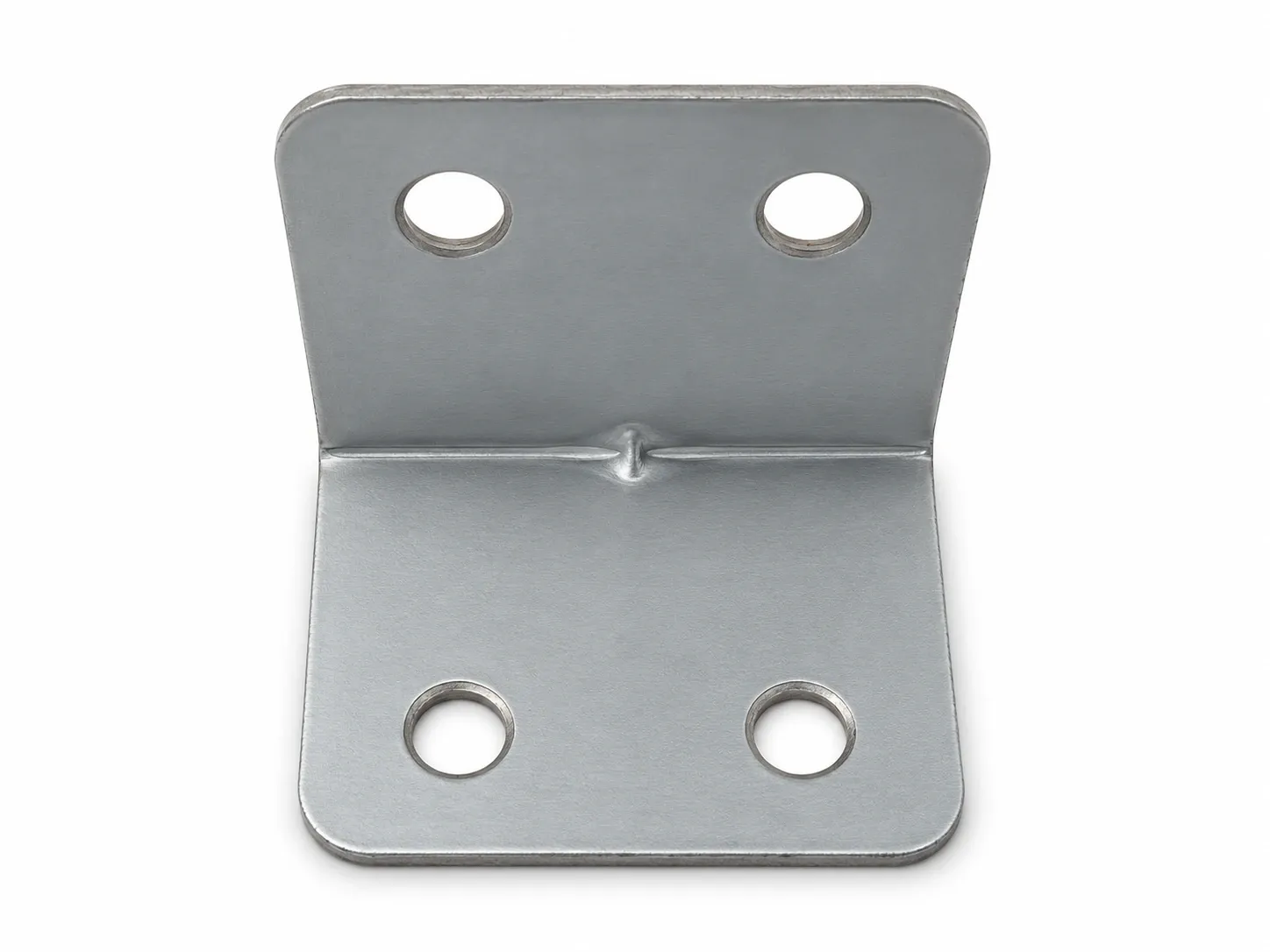
Send the mounting requirements with the bracket drawing
A useful enquiry explains what the bracket connects, where it is fixed and which interfaces cannot move. Add the intended quantity and the checks required for sample approval. Unresolved dimensions can be marked for review rather than guessed from a product photo.