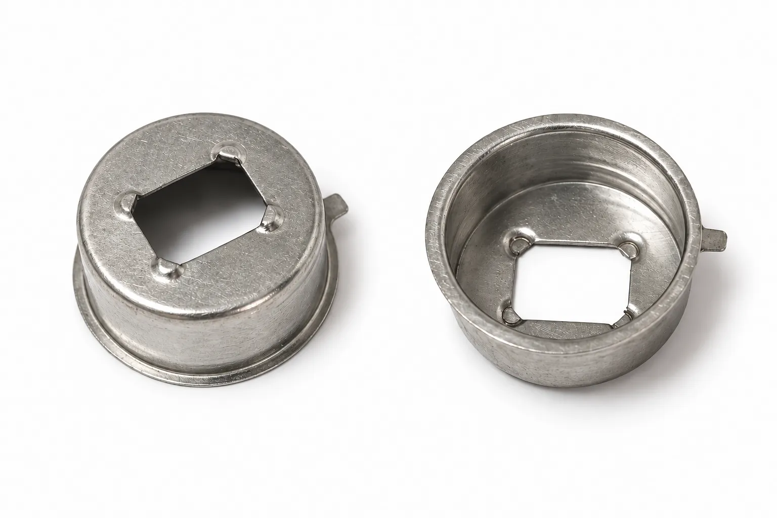
Why combine a round shell with a square opening?
This sample combines a shallow circular cup with a large square end opening. Local pressed features are visible near the opening corners, and a small tab projects from the rim. The round wall and square aperture can serve different interfaces: an outer circular installation space and clearance for an internal component or connection.
The assembly drawing must establish whether the opening contacts anything, whether the local features retain a component and whether the tab controls orientation. Similar shape alone does not establish replacement compatibility with a particular product.
Potential product families
Small electrical controls, appliance mechanisms and instrument interfaces are useful starting points. Metal covers are used in these fields, but this combination of features does not identify the sample. The following are application hypotheses for discussion.
| Potential product family | Reason to investigate | Confirmation still needed |
|---|---|---|
| Switch mechanism or relay-component cover | Shallow cavity surrounds a mechanism; opening may clear an insulating base or moving interface | Mating outline, movement, electrical clearances, conductive contacts and retention. |
| Thermostat-related mounting or protective shell | Established thermostat designs combine metal cups with insulating internal components | Family-level analogy only. This square-hole sample has not been matched to a thermostat model; verify sensing location and internals. |
| Instrument or sensor-interface cover | Circular outside can meet a round mounting space while the aperture clears an interface | Insertion direction, space, corner clearance, lead protection and grounding or insulation. |
| Small actuator end guard around a non-round link | Opening can clear a non-round connection; tab may orient installation | Geometry-based hypothesis. Verify movement, retention, load and contact before considering torque transmission. |
Specify more than the side length
Decide whether the mating component simply passes through the opening or locates against its edges. Clearance requires checking the complete component envelope. Location also requires identifying the contacting edges, permitted movement and any other locating features.
Width, height, corner profile, position within the round shell and orientation relative to the tab can all affect assembly. An opening with rounded corners may interfere with a near-square mating component even when the nominal side length appears sufficient. Compare actual cross-sectional profiles.
Relate burr direction and edge condition to insertion and use. Edges near insulation or wiring need an agreed condition that avoids damage. Electromagnetic shielding cannot be established from shape alone; conductive material, openings, joints and grounding affect the complete assembly.
Define the tab and local features by their function
A tab may help orient the part, but a projecting tab alone does not establish retention or resistance to rotation. Show its relationship to the mating slot, bracket or contact face. State whether it is bent during assembly, carries load or must retain its shape after installation.
Define the local features around the opening from the intended design and sample. If they hold an insert, establish contact locations, permitted deformation and assembly sequence. Avoid assigning an unconfirmed staking, welding or locking function from photographs.
Manufacturing and sample checks
A candidate route is cup drawing followed by aperture production, tab trimming and local forming; another sequence may suit the drawing. Cup support, aperture position and corner material condition influence tooling choices. The actual route needs drawing review and sampling.
Check outside diameter, usable depth and rim seating together with the complete opening profile, tab location and their relative orientation. Use the mating components to check insertion, corner interference, movement and wall deformation after retention. Insulation, temperature, grounding or ingress requirements follow the component and end-product acceptance conditions.
Material grade, thickness and finish remain separate inputs. Photographs show geometry and appearance; they do not establish alloy or corrosion performance.
Start with the mating component
Send shell and mating-part drawings, sketches or photographs. Explain what passes through the opening, where the tab meets another part and whether anything moves inside. Add expected quantities and describe practical concerns such as difficult insertion, unwanted rotation or scratched insulation.
Specify whether delivery covers a bare metal part, a finished shell or an assembly with other components. Samples and repeat batches should refer to the same drawing revision and agreed acceptance conditions.